
Direct Answer
How do you test a robot joint module under dynamic load?
Test a robot joint module under dynamic load by mounting the complete motor–reducer–encoder–driver assembly in its intended orientation, applying a defined bidirectional torque-speed-position sequence at the output, and synchronizing command, output torque, output angle/speed, motor current, voltage, temperature, vibration, alarms, and time. Evaluate tracking, reversal, backdriving, lost motion, torsional stiffness, thermal drift, and endurance against pre-agreed conditions, tolerances, invalid-run rules, and acceptance records.
Use the output-side application cycle as the starting point. A motor-only rating or one peak joint torque does not define the fixture, loading, dynamics, thermal duty, measurement range, or acceptance method.
Dynamic Test Sequence
Seven steps from application load to signed result.
| Step | Required definition and evidence |
|---|---|
| 1. Freeze the DUT boundary | Identify the motor, reducer, driver, encoder, brake, torque sensor if integrated, housing, bearings, output flange, firmware, and mounting orientation included in the result. |
| 2. Define the application load | Translate the robot task into output-side torque, speed, position, direction, external inertia, gravity or holding load, cycle timing, dwell, reversal, repetition, and thermal conditions. |
| 3. Establish the reference state | Record identity, alignment, zero, warm-up, cooling, lubricant state where relevant, controller settings, safety limits, and low-risk baseline points before dynamic loading. |
| 4. Apply the dynamic sequence | Run the agreed ramps, steps, reversals, holds, back-drive segments, application cycles, and recovery periods without exceeding the approved output-side envelope. |
| 5. Synchronize the channels | Align command, output torque, output angle and speed, motor current and voltage, temperature, vibration, controller status, alarms, and a common time base. |
| 6. Validate each run | Apply settling, trigger, filtering, window, invalid-sample, alarm, interruption, repeat, and stop rules before calculating a metric or comparing runs. |
| 7. Compare and accept | Report raw-data references, processed curves, initial and final states, tolerances, exceptions, retests, reviewer, and sign-off against the agreed application decision. |
Acceptance Matrix
Match each joint-module metric to its stimulus and record.
| Test objective | Stimulus and condition | Required record | Acceptance definition |
|---|---|---|---|
| Output torque-speed envelope | Steady points, ramps, both directions, declared duration and cooling | Command and measured output torque/speed, electrical and thermal state, alarms | Coverage and tolerance at each agreed point; never infer the full envelope from one maximum |
| Dynamic tracking | Defined torque, speed or position steps/ramps with external inertia and load | Command and measured response on one time base, trigger, filtering, load and controller state | Project-defined error, delay, overshoot, settling or trajectory criteria |
| Reversal and lost motion | Slow bidirectional loading or position reversal through the required torque region | Input/output angle, torque, direction, preload, temperature and repeated loops | Agreed hysteresis/lost-motion definition, calculation region and repeatability |
| Torsional stiffness | Controlled output torque versus angular deflection with the required side constrained | Torque-angle curve, fixture compliance, mounting, direction, temperature and fit region | Slope or piecewise method stated with fixture correction and tolerance |
| Backdriving and holding | External output torque or motion with drive/brake states explicitly defined | Breakaway/running behavior, torque, speed, current, brake state, temperature and safety status | Application-specific backdrive or holding limits; do not substitute motor current alone |
| Thermal drift | Repeated application cycle or hold until the agreed end condition | Component/coolant/ambient temperatures plus torque, position, current and time | Temperature limits and permitted change in performance under the same comparison method |
| Endurance and degradation | Defined load sequence, repetitions, stops, inspections and recovery periods | Cycle count, events, alarms, temperatures, periodic reference checks and before/after data | Failure definition, interruption/restart rule and allowed degradation |
| Protection and recovery | Approved overload, overspeed, overtemperature, communication-loss or emergency scenarios | Trigger, system state, stop behavior, retained alarms, reset and post-event check | Safe response and documented recovery; destructive limits require a separately approved procedure |
Configuration Logic
Six decisions that define the test platform.
Test the module as an assembly
Define whether the test object is a motor only, an actuator, or a complete motor-reducer-driver-encoder joint module. The answer changes the fixture, interfaces, channels, and safety workflow.
Start from the output side
Rated and peak output torque, speed range, operating direction, duty cycle, and overload profile define the loading and mechanical design.
Make the mechanical interface explicit
An output flange, shaft, mounting orientation, coupling, guard, alignment method, and service access should be confirmed before the fixture is designed.
Connect the data to the engineering question
Torque and speed can be combined with electrical, temperature, position-related, vibration, and custom signals when those results are needed for the defined procedure.
Choose the workflow before the software
R&D characterization, endurance cycling, production QC, and EOL checks need different sequences, judgment logic, traceability, and report fields.
Plan safety around stored energy and motion
Guarding, emergency stop, interlocks, overload protection, and the allowed operating profile should be considered as part of the complete test platform.
System Scope
Loading is only one part of an integrated joint-module workflow.
The loading unit needs to match the required output-side conditions, but the full test bench also needs the right fixture, coupling, sensors, driver interface, control logic, protection, acquisition, and reporting. A request that identifies the complete module and intended result is usually more actionable than a request based on a dynamometer size alone.
For a full product overview, see the Robot Joint Module Motor Test System. For controlled loading and efficiency concepts that also apply to actuator projects, see the Motor Torque-Speed and Efficiency Testing Guide.
Reference Boundaries
Use robot and reducer references without overstating scope.
ISO 9283:1998 covers performance criteria and test methods for manipulating industrial robots, not automatic certification of a standalone joint module. ISO 9409-1:2004 defines a circular plate mechanical interface but does not assign load-carrying capacity.
Harmonic Drive's gearhead technical catalog illustrates why torsional stiffness and hysteresis/lost motion use a defined bidirectional torque–torsion procedure. Kollmorgen's robotic joint module manual shows that an integrated joint can include the motor, drive, brake, gear, feedback, thermal sensor, duty limits, interfaces, and communications. Their model-specific values are not Weiheng specifications.
Limits and Evidence Boundaries
What this guide and equipment photograph do not prove.
- ISO 9283 addresses performance criteria and test methods for complete manipulating industrial robots. It can inform terminology and system-level thinking, but it does not by itself certify a standalone joint-module result.
- ISO 9409-1 defines dimensions, designation, and marking for a circular plate interface; it explicitly does not correlate the interface with load-carrying capacity. Fixture strength and load limits require project evidence.
- Backdriving torque, lost motion or hysteresis, backlash, torsional stiffness, transmission accuracy, tracking error, and repeatability are not interchangeable. The test sequence, constrained side, load region, calculation, and temperature must be stated.
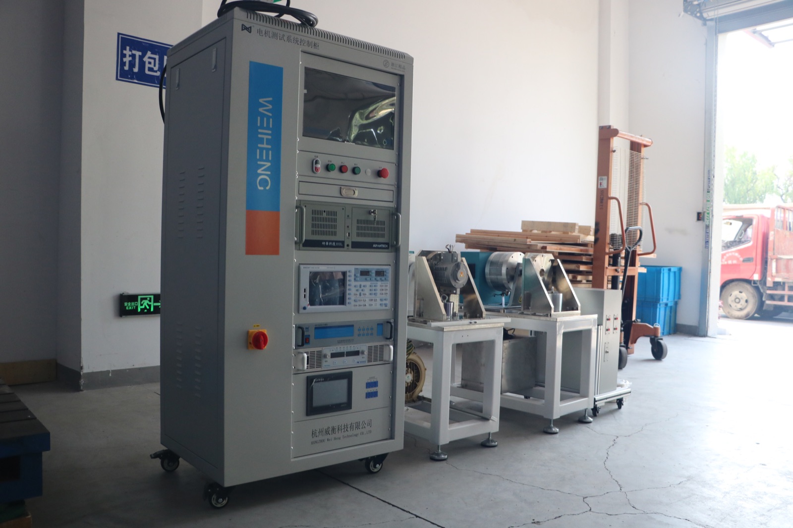
- The original Weiheng factory photograph verifies physical control, loading, fixture, and measurement equipment. It does not prove a response time, stiffness, lost motion, endurance life, accuracy, or acceptance result.
Before Quotation
Inputs that make a robotics test requirement technically actionable.
- Joint module or actuator drawing, photos, and mounting orientation
- Rated and peak output torque, rated speed, maximum speed, and duty cycle
- Motor, reducer, driver, encoder, brake, sensor, and cooling configuration
- Output flange, shaft, coupling, fixture, alignment, guarding, and access requirements
- Required torque-speed, dynamic response, endurance, reducer-related, temperature, position-related, or quality checks
- Driver interface, communication requirements, power platform, and control workflow where applicable
- R&D, laboratory, production QC, or end-of-line use case; test quantity and traceability needs
- Data fields, curve types, report language, acceptance method, and target country
Use the broader Custom Motor Test Bench Configuration Guide when the project also needs a custom safety, software, data, or factory workflow.
FAQ
Robot Joint Module Test Bench Questions
What is a robot joint module test bench?
A robot joint module test bench is a configurable system for testing an integrated actuator or joint module under controlled loading conditions. It can combine a loading unit, mechanical fixture, torque and speed measurement, electrical and driver interfaces, control and safety hardware, data acquisition, and software reporting.
Why should the reducer and encoder be included in the requirement?
A complete joint module behaves differently from a motor-only test object. The reducer, encoder, driver, brake, output interface, and module structure affect the fixture, measurement channels, sequence, and result the engineering team needs to evaluate.
Can one system support R&D and production QC?
A shared engineering base can be discussed, but R&D characterization and production QC normally need different test sequences, cycle time, traceability, pass/fail logic, and operator workflow. These requirements should be defined before configuration.
What should be sent for a robot joint module test bench quotation?
Send the module drawing, output torque and speed range, duty cycle, integrated components, driver interface, intended test items, fixture requirements, report needs, target country, and whether the system is for R&D, endurance, QC, or EOL work.
How is a robot joint module tested under dynamic load?
Mount the complete module in the intended orientation, apply the agreed bidirectional output-side torque-speed-position sequence and external inertia, synchronize command and measured channels, then judge tracking, reversal, thermal behavior, protection, and degradation with stated conditions and tolerances.
Are backdriving torque, lost motion, and torsional stiffness the same?
No. Backdriving describes torque or force needed to move the output under defined drive and brake states; lost motion describes a bidirectional position or torsion loop; torsional stiffness relates applied torque to angular deflection over a stated region.