
Direct Answer
How should robot joint temperature rise and endurance be tested?
Define the complete actuator boundary, then replay the intended output torque, speed, position, acceleration, hold, reversal, dwell, and recovery sequence under a stated ambient, mounting, enclosure, cooling, supply, and controller condition. Record synchronized temperature, torque, speed, position, current, voltage or bus condition, controller state, alarms, limits, and time.
Thermal equilibrium must use a project-approved sensor location, stability rule, observation window, and stop condition; there is no universal threshold for every integrated joint. Endurance testing repeats an approved cycle with periodic reference checks and before-after evidence. A cycle count or elapsed time without those boundaries is not a service-life result.
Thermal Boundary
Freeze six boundary groups before comparing temperature data.
| Boundary group | What the project should declare |
|---|---|
| DUT and configuration | Complete actuator, motor, reducer, encoder, brake, drive, firmware, lubricant state, and revision included in the result |
| Mounting and enclosure | Flange, fixture, robot-link surrogate, fasteners, orientation, enclosure, cable routing, and nearby heat paths |
| Ambient and cooling | Ambient reference, airflow, natural or forced cooling, coolant condition where applicable, and stabilization before the run |
| Electrical and control | Supply or bus condition, current and torque limits, control mode, tuning, switching state, protective limits, and regenerative behavior |
| Mechanical duty | Output torque, speed, position, acceleration, direction, dwell, hold, reversal, inertia, external load, and cycle timing |
| Measurement and stop rules | Sensor locations, sampling and synchronization, thermal-equilibrium definition, alarm handling, safety limits, invalid-run rules, and operator responsibility |
Duty-Cycle Translation
Turn the robot task into a repeatable time history.
Do not replace an application cycle with one peak torque value or an undefined continuous run. Preserve the sequence and recovery conditions that create the thermal load.
| Cycle segment | Inputs and states to preserve |
|---|---|
| Acceleration and motion | Torque, speed, acceleration, direction, position range, inertia, duration, and electrical input during the move |
| Steady load | Output torque and speed, hold time, cooling state, controller limits, and expected heat-rejection condition |
| Position hold or near-zero speed | Holding torque, current, brake state, controller behavior, duration, and the risk that low speed changes cooling or losses |
| Deceleration and reversal | Regeneration path, voltage response, negative torque, reversal frequency, dwell, and protection state |
| Idle and recovery | Power state, zero-load behavior, fan or coolant state, recovery time, restart condition, and temperature before the next cycle |
Thermal Equilibrium
State the sensor, stability rule, window, and stop condition.
Thermal equilibrium is useful only when the project names which temperatures matter, how they are sampled, what stability rule is evaluated, over what observation window, and whether the load, cooling, ambient, and controller state remain unchanged. A housing surface, motor winding estimate, reducer case, bearing region, driver, coolant, and ambient channel do not represent the same thermal boundary.
If the required equilibrium criterion is not reached before a safety limit, alarm, controller derating, measurement failure, or project time limit, retain the run and the stop reason. Do not silently label an incomplete run as equilibrium.
Cold and Hot Comparison
Compare like with like at two declared thermal states.
Use the same DUT revision, fixtures, measurement planes, controller settings, cycle, sign conventions, sampling, calculations, and acceptance method for the cold and hot checkpoints. Record the starting thermal state and any change in torque, speed, current, efficiency, tracking, mechanical metric, vibration, noise, alarm, limit, or protection behavior required by the project.
A hot-state difference belongs to the complete tested path. It should not be assigned to the motor, reducer, lubricant, encoder, drive, fixture, or software without supporting evidence.
Endurance Workflow
Seven steps from the baseline to a reviewable endurance record.
| Step | Required definition and evidence |
|---|---|
| 1. Freeze the baseline | Record the as-built DUT, configuration, mounting, software, thermal state, and the reference checks that will be repeated later. |
| 2. Translate the application cycle | Convert the robot task into torque-speed-position-time segments, holds, reversals, dwell, recovery, ambient, cooling, and expected variants. |
| 3. Define limits and interruption rules | Name temperature, electrical, mechanical, vibration, noise, tracking, alarm, guarding, and operator limits without inventing a universal threshold. |
| 4. Run a thermal characterization | Execute the declared cycle and determine whether the project-specific equilibrium or stopping criterion can be evaluated with the chosen sensors and duration. |
| 5. Start the endurance sequence | Repeat the approved cycle while retaining cycle count, temperatures, loads, controller states, alarms, interruptions, and restart conditions. |
| 6. Perform periodic checkpoints | At named intervals, return to the same reference method and compare thermal, electrical, mechanical, functional, or acoustic indicators required by the project. |
| 7. Close with before-after evidence | Retain the final reference checks, changes, exceptions, failed or incomplete runs, inspections, disposition, and the exact acceptance decision. Test duration alone is not a life claim. |
Required Record
Keep the conditions behind the curve, alarm, and checkpoint.
- Ambient plus agreed winding, housing, reducer, bearing, driver, coolant, fixture, or surface temperature channels
- Synchronized output torque, speed, position, direction, current, voltage or bus condition, power, controller state, limits, alarms, and time
- DUT identity, firmware, lubricant, mounting, fastener, orientation, cable, enclosure, airflow, coolant, and fixture revisions
- Sensor type, location, attachment, sampling, calibration reference, filtering, lag treatment, missing-data and invalid-run rules
- Cycle version, segment timing, repeats, interruptions, restarts, stop reason, inspection event, maintenance action, and reviewer
- Cold baseline, hot-state comparison, periodic checkpoint results, raw file, processed curve, calculation version, acceptance rule, and sign-off context
Weiheng Thermal and Durability Traceability Plan v1.0
Keep the result connected to identity, raw data, processing, exceptions, and approval.
A thermal or endurance result is traceable only when the DUT, released recipe, channel passport, raw data, processing version, first stop trigger, invalid-run decision, retest relationship and approval record remain linked. Raw data and processed data are related but not interchangeable.
| Traceability layer | Minimum controlled record |
|---|---|
| Identity and baseline | DUT serial/configuration, included components, fixture, controller, firmware, software, recipe and method revisions |
| Execution | Run ID, operator, time, initial state, environment, duty-cycle version, channel passport, witness and event markers |
| Raw and processed data | Immutable raw-channel reference plus filters, resampling, formulas, excluded intervals, calculation version and generated dataset ID |
| Exceptions and retests | First trigger, dependent alarms, invalid/abort/deviation reason, operator action, affected interval, correction and linked retest |
| Decision and change | Requirement, tolerance source, result, uncertainty boundary where applicable, approval status, reviewer and effective revision |
Open the printable Thermal, Durability and Data Traceability Plan v1.0.
Weiheng NVH Method Passport v1.0
Compare endurance NVH only with the state, reference, acquisition, and processing frozen.
Before-and-after NVH evidence can support an endurance comparison only when the operating state and acquisition chain are comparable. Weiheng keeps housing vibration, sound pressure, rotational orders, spectra and transient events as named outputs; an observed peak or change is not assigned to a gear, bearing, motor or controller without additional isolation evidence.
| Comparison control | Required boundary |
|---|---|
| DUT and fixture | Keep the DUT revision, support, sensor mounting, orientation, cable routing, controller and brake state fixed or disclose the change |
| Operating state | Use comparable speed/load trajectories, direction, thermal state and lubrication condition before and after endurance |
| Reference and acquisition | Retain sensor locations/axes, microphone geometry where used, rotational reference, timebase, sampling, anti-aliasing and clipping checks |
| Processing | Freeze windows, filtering, averaging, spectral/order settings and software version; retain raw time data |
| Interpretation | Report vibration, sound, order and event observations separately; a changed peak is not a component diagnosis or remaining-life result |
Open the printable Robot Joint NVH Measurement Method Passport v1.0.
Weiheng Test-System Context
Connect the duty cycle, controlled loading, monitoring, protection, and reporting.
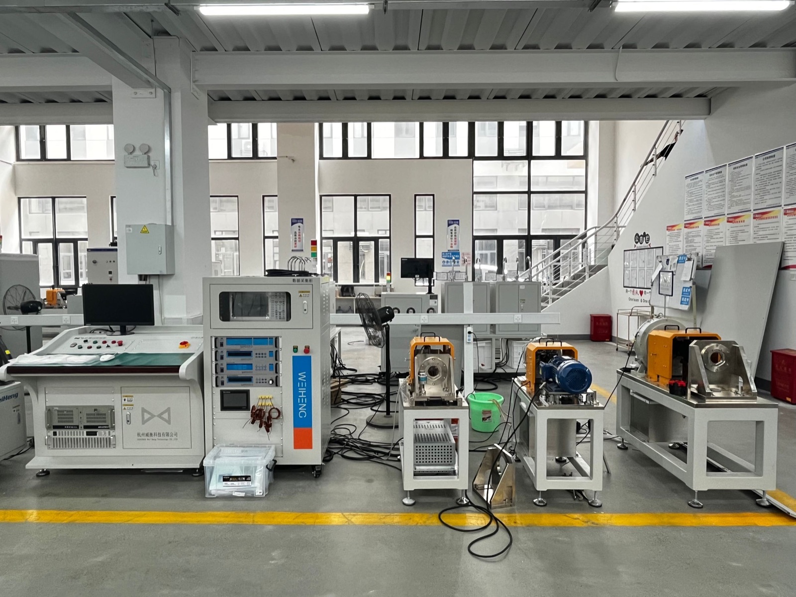
Weiheng can configure robot joint test platforms around a declared actuator, output load profile, drive interface, mounting, cooling, temperature channels, safety and interruption logic, repeated sequence, checkpoints, and report workflow. The required equipment and method remain project-specific; the factory photograph verifies physical system integration only.
Use the Robot Joint Module Test Bench Configuration Guide for the complete platform boundary, the Robot Joint Backlash and Stiffness Test Guide for mechanical checkpoints, and the Motor Test Data and Acceptance Planning Guide for traceable records and sign-off stages.
Reference Boundaries
Use public engineering sources without copying product limits into a Weiheng claim.
Kollmorgen's RGM User Guide shows that an integrated robotic joint can include motor, drive, brake, strain-wave gear, feedback, thermal sensing, firmware, duty-cycle, and product-specific thermal limits. maxon's Thermal Assessments explains thermal time constants and why transient temperature behavior depends on duration and the thermal system.
These sources support test-boundary and method design. Their model values, limits, ratings, life statements, and examples are not Weiheng specifications and are not copied into a customer acceptance criterion.
FAQ
Robot Joint Thermal and Endurance Test Questions
How should temperature rise be tested on an integrated robot joint?
Replay a declared torque-speed-position-time duty cycle with the actuator, mounting, drive limits, ambient, cooling, and sensor locations fixed. Record synchronized thermal, electrical, mechanical, controller, alarm, and timing data. Report temperature rise only with those conditions.
What is thermal equilibrium in a robot actuator test?
It is a project-defined condition showing that the monitored temperature behavior has stabilized sufficiently for the intended decision. The sensor location, sampling, rate or window rule, duration, ambient, load cycle, cooling, and stop condition must be stated; this guide does not impose one universal threshold.
How should cold and hot robot-joint behavior be compared?
Use the same DUT, measurement planes, control settings, fixtures, load sequence, channel definitions, and calculation methods at declared starting and hot states. Record any limit, derating, drift, alarm, or protection change rather than attributing every difference to one component.
Does an endurance test prove robot-joint service life?
Not by duration or cycle count alone. A defensible endurance result needs a representative cycle, stated acceleration or usage model where applicable, checkpoints, failure and interruption rules, inspections, retained raw data, and a project-approved interpretation. This page does not publish a life claim.
What should be sent for a robot joint thermal or endurance test proposal?
Send the actuator drawing and revision, integrated components, mounting and cooling, supply and drive details, torque-speed-position-time cycle, ambient range, temperature points, limits, cycle or duration target, checkpoint plan, stop rules, required reports, and target country.