Servo Motor Manufacturers
Validate torque response, speed response, rated performance, repeatability, and quality consistency before delivery.
 Request a Quote
 Servo Motor Dynamic Performance Testing
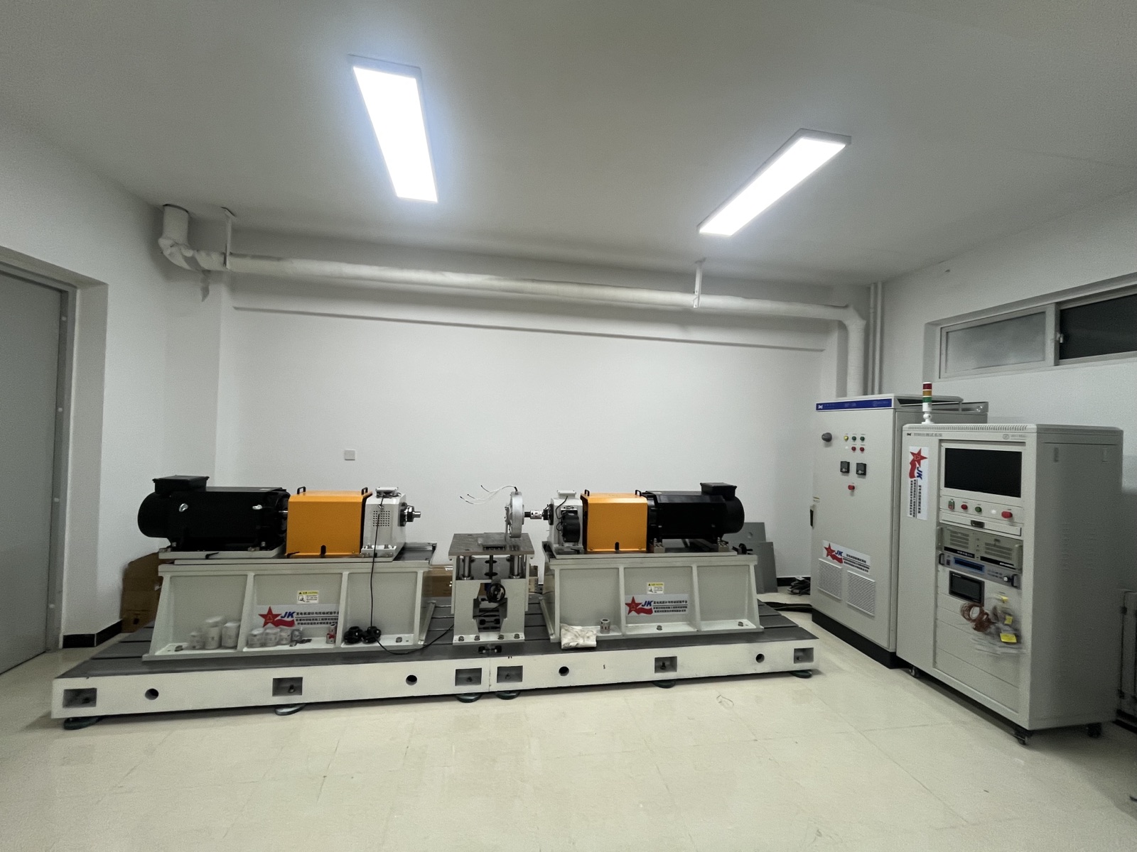
Weiheng designs custom servo motor test systems for dynamic response, torque-speed performance, efficiency, temperature rise, endurance, and production quality testing.
The loading unit, measurement range, drive interface, fixture, software, and report workflow are configured around your servo motor and test procedure.
Direct Answer
A servo motor test system measures servo motor performance under controlled loading conditions, including torque-speed behavior, torque response, speed response, efficiency, temperature rise, endurance, and repeatability. Weiheng configures the system according to motor data, drive interface, fixture, test workflow, software output, and production or laboratory needs.
Application Fit
Validate torque response, speed response, rated performance, repeatability, and quality consistency before delivery.
Build test platforms for servo motors used in motion control, CNC equipment, packaging machinery, and precision manufacturing.
Measure dynamic behavior, overload capability, temperature rise, and performance consistency for servo-driven motion modules.
Support motor-control development, control strategy comparison, parameter tuning, and custom validation procedures.
Configure EOL or QC workflows with automatic test sequences, pass/fail logic, traceable data, and report output.
Test Coverage
Test sequences are confirmed against the servo motor, drive, control workflow, and quality standard.
System Architecture
Selected for servo motor torque, speed, power, response requirement, duty cycle, and test duration.
Synchronized mechanical measurement supports torque-speed curves, response analysis, and repeatability checks.
Voltage, current, input power, output power, and efficiency channels can be aligned with mechanical data.
Optional integration with servo drive signals, operating modes, communication needs, and project-specific workflows.
Custom fixture, shaft coupling, base, guard, alignment structure, and service access around the servo motor.
Automated sequences, curve display, data storage, pass/fail judgment, English reports, and custom report formats.
Engineering Inputs
| Servo motor data | Rated power, rated torque, peak torque, rated speed, maximum speed, encoder or drive interface |
|---|---|
| Dynamic behavior | Torque response, speed response, start-stop sequence, forward/reverse operation, and overload profile |
| Measurement channels | Torque, speed, voltage, current, power, efficiency, temperature, vibration, and custom signals |
| Mechanical interface | Shaft drawing, flange, coupling, mounting direction, fixture, guard, and alignment requirement |
| Test workflow | R&D validation, laboratory testing, production QC, EOL testing, or customer-specific procedure |
| Software output | Curves, raw data, automatic report, pass/fail logic, traceability, and English workflow customization |
Before Configuration
To configure a custom servo motor test bench, define the complete torque-speed envelope, efficiency measurement boundary, dynamic duty, mechanical interface, cooling, controls, data, and acceptance requirements. Rated power alone is not enough.
| Decision input | What the buyer should provide | Why it changes the configuration |
|---|---|---|
| DUT and operating envelope | Motor type, datasheet, rated and peak power and torque, rated and maximum speed, voltage/current, permitted duration, and operating quadrants | Sizes the loading unit, measurement ranges, coupling, cooling, and protection limits |
| Efficiency boundary | Motor only, drive + motor, or complete system; identify the electrical input plane and mechanical output plane | Defines where electrical power is measured and which efficiency result can be reported |
| Dynamic profile | Torque/speed command, load or inertia, acceleration and deceleration, duration, controller state, and regeneration requirements | Defines loading dynamics, control architecture, synchronized acquisition, and protection |
| Mechanical interface | Flange, shaft, key or spline, center height, drawings, DUT mass, mounting, and supported variants | Defines fixtures, alignment, coupling, guarding, and changeover design |
| Thermal and utilities | Cooling method, coolant conditions, ambient limits, plant power, installation space, and safety constraints | Defines cooling, electrical supply, layout, and site protection scope |
| Measurement and data | Required variables, measurement or acceptance target, synchronized channels, raw data, reports, and pass/fail rules | Defines sensors, electrical measurement, DAQ, software, and traceability |
| Delivery and acceptance | Destination, applicable requirements, FAT/SAT scope, training, installation, language, and interface responsibilities | Defines documentation, commissioning, verification, and project boundaries |
Rated values describe a continuous operating point under stated conditions. Peak torque, maximum speed, and permitted duration define intermittent extremes. Final selection therefore uses the complete torque-speed envelope, duty cycle, thermal conditions, and agreed safety margin rather than rated power alone.
Motor-only efficiency compares electrical power at the motor input with shaft mechanical output. Drive-and-motor efficiency uses power at the drive input and shaft output. A complete-system boundary may include agreed auxiliary loads. The test plan should identify measurement planes, synchronized channels, thermal conditions, filtering, averaging, and invalid-run rules before results are compared.
Send the motor datasheet and mechanical drawing, rated and peak values, required tests, efficiency boundary, dynamic duty, control and encoder interfaces, cooling and utilities, measurement and acceptance targets, software and data outputs, destination, and FAT/SAT scope. Mark unknown items to be confirmed instead of inserting guessed values.
Engineering Value
Weiheng aligns loading, measurement, drive interface, fixture design, software logic, and reports into one servo motor testing workflow.
Servo test workflows can be configured around torque response, speed response, and repeatability.
Mechanical and electrical signals are aligned for performance analysis and quality judgment.
Fixtures, test steps, drive interface, report format, and pass/fail rules can follow the buyer's process.
The same engineering base can support validation benches, laboratory systems, QC benches, or EOL stations.
Configuration Resource
Torque response and speed response need an agreed load profile, drive interface, fixture, synchronized channels, and report workflow.
Use a practical checklist for torque and speed response, start-stop behavior, reversal, loading, and report inputs.
Open the servo response guideReview controlled loading and synchronized measurement concepts for output performance evaluation.
Open the testing guideFAQ
A servo motor test system measures servo motor performance under controlled loading conditions, including torque-speed behavior, torque response, speed response, efficiency, temperature rise, endurance, and repeatability.
Yes. The test workflow can be configured for torque response, speed response, start-stop behavior, forward/reverse operation, and project-specific dynamic profiles.
Weiheng can discuss motor-only testing or integration with servo drive signals and operating workflows depending on the project interface.
Send the motor datasheet and mechanical drawing, rated and peak operating values, required tests, efficiency boundary, dynamic duty, control and encoder interfaces, cooling and utilities, measurement and acceptance targets, software and data outputs, destination, and FAT/SAT scope. Mark unknown items to be confirmed.
Yes. Weiheng can configure QC or EOL workflows with automatic sequences, pass/fail judgment, traceable data, and report output.
Yes. English interface, automatic test sequences, curve display, data storage, pass/fail logic, and custom report templates can be discussed.
Request a Proposal
Share rated power, rated torque, peak torque, maximum speed, drive interface, motor drawing, test items, application, target country, and report requirements.