Steering and EPS motors
Define the motor or assembly boundary, controller, mechanical interface, direction, loading, operating sequence, thermal conditions, required signals, and functional evidence.
 Request a Quote
 Automotive Component Testing
Plan the system around the complete component, motor or controller, interfaces, operating sequence, required evidence, fixture, development stage, and acceptance boundary.
Route motor-only, assembly performance, quality-control, and production EOL needs before defining hardware.
Direct Answer
Automotive component motor testing evaluates a motor-driven component or assembly under defined electrical, mechanical, hydraulic, thermal, or control conditions. The test route depends on the DUT boundary, vehicle-level decision, interfaces, operating sequence, required evidence, development or production stage, and acceptance plan.
Component Routing
Start with the complete DUT and the decision the test must support, then define the fixture, conditions, signals, software, and records.
Define the motor or assembly boundary, controller, mechanical interface, direction, loading, operating sequence, thermal conditions, required signals, and functional evidence.
Define supported variants, fixtures, connectors, travel or load boundary, direction and start-stop sequence, current behavior, functional checks, identification, and records.
Define the pump, motor or controller, working liquid, hydraulic circuit, operating points, ports, fixtures, safety, calculations, curves, and reports.
Define the complete assembly, drive and communication interface, load or process condition, cooling, electrical and mechanical evidence, safety, and test sequence.
Project Definition
| DUT and assembly boundary | Component type, model variants, motor, controller, gearbox or mechanism, sensors, harness, drawings, mounting, connectors, cooling, and buyer-supplied items. |
|---|---|
| Vehicle-level function | The decision the component must support, without assuming a specific OEM requirement, regulation, certification, or customer acceptance standard. |
| Operating sequence | Directions, starts, stops, steady points, ramps, cycles, loads, travel, pressure or other process conditions, temperatures, repetitions, and exception paths. |
| Required evidence | Electrical and mechanical values, functional state, curves, temperatures, vibration or noise channels, fault behavior, pass/fail results, raw data, and reports. |
| Fixture and interfaces | Positioning, coupling, ports, seals, connectors, communication, handling, guarding, operator access, utilities, changeover, and supported variants. |
| Development or production route | Flexible engineering measurement, design validation, sampled quality checks, or repeatable EOL testing with identification, limits, traceability, and factory handoff. |
| Review and acceptance | Test article, conditions, sequence, outputs, supplied items, exclusions, documentation, review method, exceptions, and site-dependent work. |
Test Route
Use configurable loading or process conditions, synchronized measurements, engineering access, variant comparison, raw data, and documented procedures.
Use a dedicated system when the assembly interface, operating condition, fixture, controller, process circuit, or evidence differs materially from a general motor bench.
Use controlled samples or production units, stable fixtures and recipes, agreed checks, limits, exception handling, identification, and traceable records.
Use repeatable handling and sequences, automatic decisions, traceability, operator workflow, reports, and confirmed factory interfaces.
Related Systems
Use Motor Testing Equipment for equipment-route selection, Pump Performance Test System for liquid-circuit projects, and Motor End-of-Line Test System for production release.
Compare development and production priorities in R&D Test Bench vs EOL Test System.
FAQ
It is the planned functional and performance evaluation of a motor-driven automotive component or assembly under defined electrical, mechanical, hydraulic, thermal, or control conditions. The test route follows the DUT boundary, vehicle-level decision, interfaces, required evidence, development stage, and acceptance plan.
Projects may involve steering or EPS motors, seat and comfort actuators, pumps, compressors, fans, window or door drives, and other motor-driven assemblies. Each component needs its own confirmed boundary, fixture, interfaces, conditions, evidence, and safety review.
Motor-only testing focuses on the motor boundary. Component testing may also include a controller, gearbox, mechanism, pump or process circuit, sensors, harnesses, communication, fixtures, functional sequences, and assembly-level acceptance evidence.
Choose an R&D route for flexible engineering measurements and design comparison. Choose an EOL route for repeatable unit handling, fixed checks, limits, pass/fail results, identification, traceability, and production handoff. Some programs need both.
Provide the component and motor or controller, variants, drawings, interfaces, operating sequence and conditions, required measurements and functional checks, fixture and site needs, development or production stage, target country, and acceptance method.
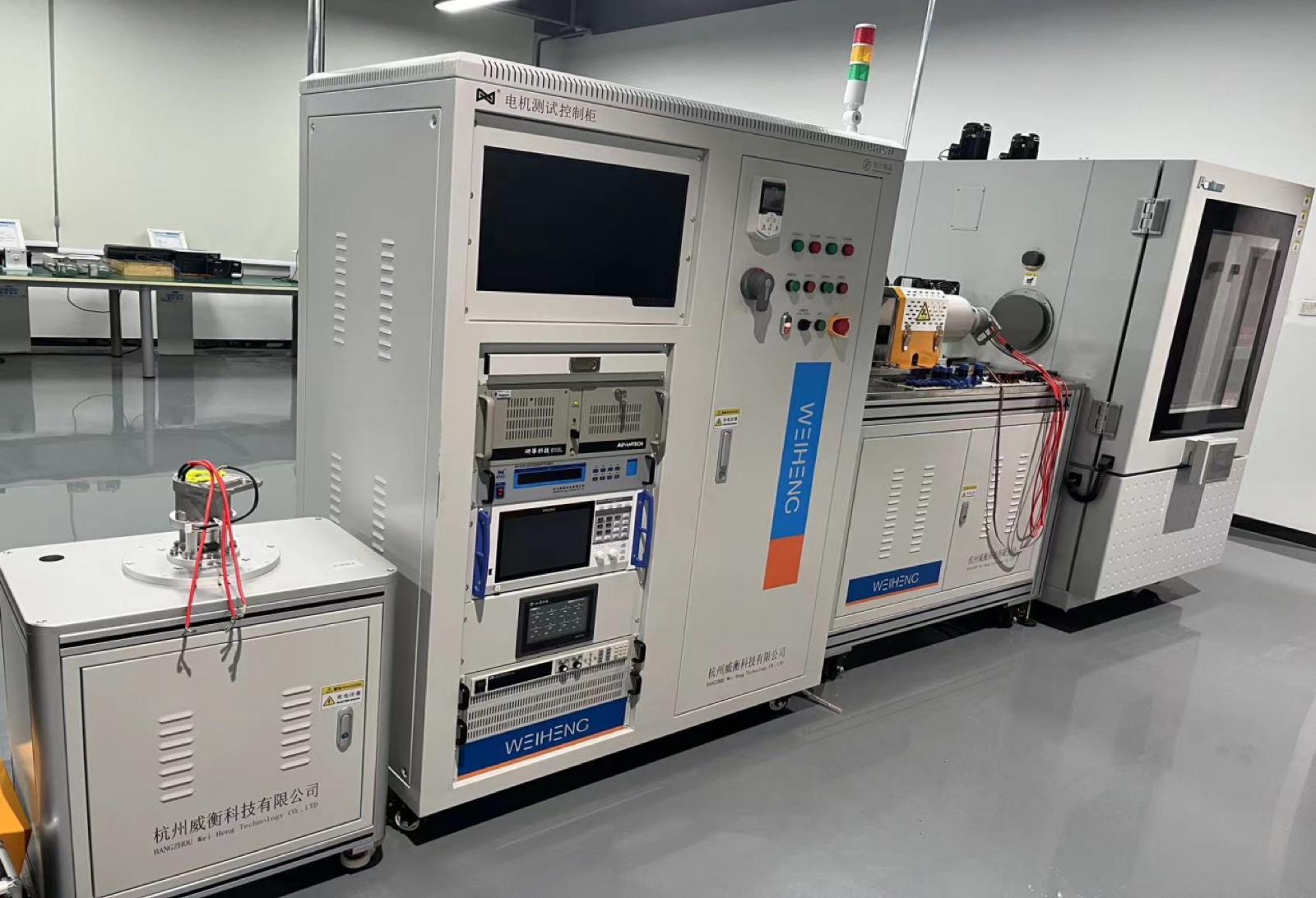
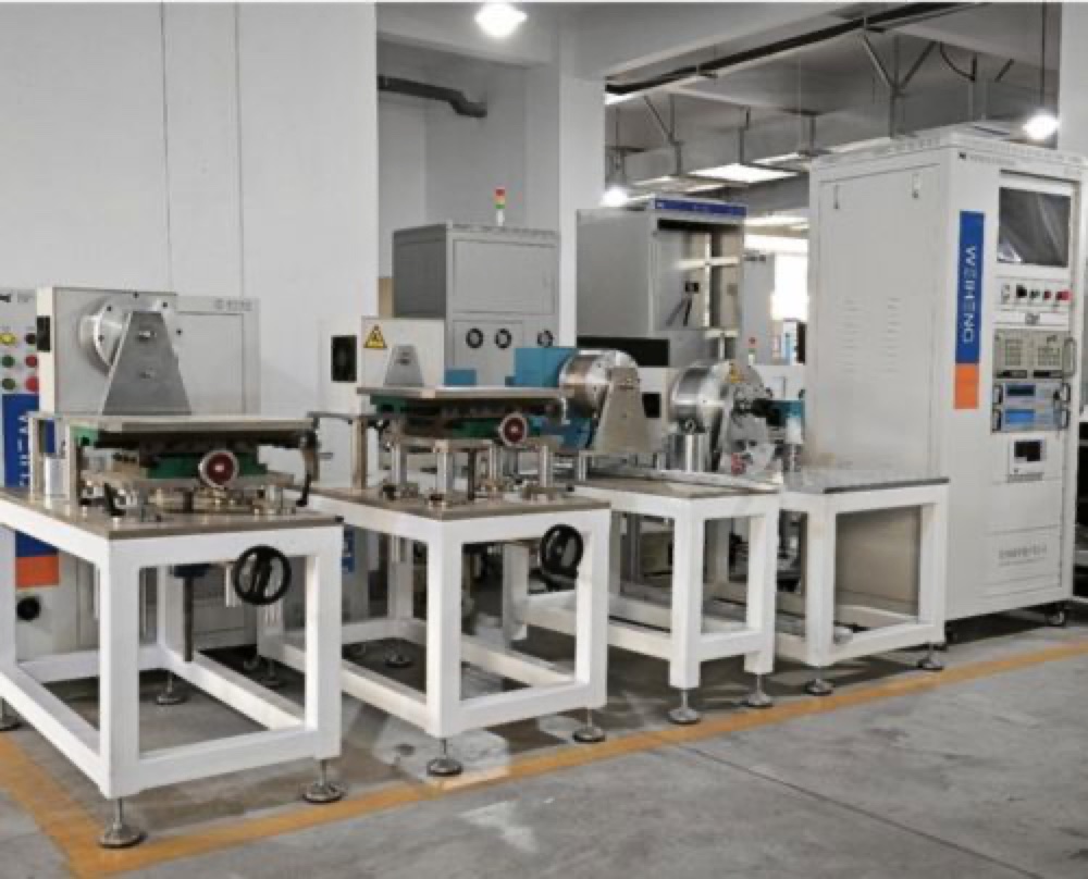
No. The photographs confirm visible Weiheng equipment and fixture integration. They do not prove an OEM relationship, regulation, certification, range, accuracy, cycle time, or project acceptance result.
Request a Proposal
Share the component and motor or controller, variants, drawings, interfaces, operating sequence, required measurements and functional checks, development or production stage, target country, and acceptance method.