
Direct Answer
How do you select a dynamometer for a PMSM motor test bench?
Select a PMSM test-bench dynamometer by plotting every motoring and generating torque-speed point with its duration, then checking continuous and peak power, maximum speed, low-speed loading, field-weakening operation, combined inertia, cooling, control modes, energy flow, mechanics, measurement range, and protection. Verify the supplier's complete envelope and acceptance method; maximum torque, speed, and power values cannot be assumed to occur simultaneously.
A dynamometer is the controlled loading unit inside a wider system. Read motor test bench vs motor dynamometer before comparing complete proposals.
Selection Criteria
Six decisions that determine a suitable dynamometer.
Torque-speed envelope
Plot continuous and peak torque against speed. Confirm every required operating point instead of comparing one rated torque or power value.
Duty cycle and duration
Define how long each load point, sweep, overload, or cyclic sequence runs. Continuous thermal demand can differ greatly from a short peak condition.
Dynamic requirement
State whether the system will hold steady points, run ramps, repeat drive cycles, or evaluate fast torque and speed changes.
Mechanical system
Provide shaft, flange, mounting direction, coupling, alignment, guard, and expected fixture changeover information.
Control and integration
Define torque or speed control, direction of rotation, regenerative operation when required, controller communication, synchronized channels, and report workflow.
Site and cooling
Confirm power supply, ambient conditions, cooling medium, available space, exhaust or heat rejection, and laboratory safety requirements.
Build or Buy Decision
Should an EV team build or buy a motor dynamometer test bench?
The decision is not a comparison between a low component price and a complete-system quotation. Compare who will own the torque-speed envelope, mechanics, controls, electrical measurement, cooling, safety, software, commissioning, acceptance, and lifecycle support. An internal build may suit exploratory research when the team can own every subsystem and iteration. A supplied system is more appropriate when the project needs a defined engineering boundary, delivery record, and acceptance method.
| Decision factor | Internal build path | Configured supplier path | Evidence to compare |
|---|---|---|---|
| Test objective and schedule | A research prototype may justify an internal build when the team can accept iteration and owns the learning objective. | A configured supplier system fits when the team needs a reviewable delivery scope, integration plan, commissioning boundary, and acceptance record. | Named test decisions, required operating envelope, delivery milestone, and acceptance outputs |
| Engineering ownership | The buyer owns loading-unit selection, mechanics, controls, acquisition, software, protection, integration, and ongoing troubleshooting. | Responsibilities are divided between buyer inputs and supplier responses, with deviations and exclusions made visible before design release. | Responsibility matrix, interfaces, assumptions, exclusions, and change-control route |
| Safety and energy flow | The internal team designs guarding, overspeed protection, interlocks, emergency stop, cooling, and motoring or regenerative energy handling. | The supplier proposes the integrated safety and energy path for review against the stated motor, site, and operating modes. | Risk review, protection logic, energy-flow diagram, utilities, and site conditions |
| Measurement and traceability | The team defines sensors, ranges, synchronization, calibration, calculations, raw-data retention, software, and report version control. | The proposal should connect instruments, data handling, report fields, and acceptance evidence to the declared measurement boundary. | Channel list, measurement definitions, calibration records, raw-data example, and report template |
| Lifecycle and support | The buyer maintains component compatibility, spares, software, documentation, operator knowledge, and future modifications. | The supplier scope can include documentation, training, commissioning, service boundaries, and controlled options when these are agreed in the contract. | Maintenance plan, documentation set, training scope, spare strategy, and support exclusions |
For the complete system boundary, review the custom motor test bench configuration guide and the dynamometer test bench before preparing the RFQ.
Envelope Review
Check every operating region, not three independent maximum values.
| Operating region | Buyer input | Selection check |
|---|---|---|
| Zero and low speed | Required holding, starting, cogging, breakaway, or low-speed torque; duration and direction | Confirm the selected loading technology and control mode can create and measure the requested condition. |
| Constant-torque region | Torque-speed points, continuous and peak duration, cooling and stabilization | Check torque, current, thermal and measurement limits at every required point. |
| Constant-power or field-weakening region | Maximum test speed, torque available at speed, power, DC-link/controller condition and duration | Do not infer high-speed capability from rated power or maximum speed alone. |
| Transient and reversal | Ramp, step, acceleration, deceleration, reversal, repetition and stop conditions | Check combined inertia, control bandwidth, driveline mechanics, energy flow and protection together. |
| Generating or back-drive operation | Which machine drives, required quadrants, regenerative behavior, DC-bus/grid or dissipation path | Define where energy goes and how overvoltage, loss of load and emergency stop are handled. |
| Endurance cycle | Complete time history, dwell, repetition, ambient and cooling states | Use the cycle to evaluate continuous heat rejection and recovery, not only peak ratings. |
Proposal Evidence
What should a dynamometer proposal prove?
A model name is not enough. Ask the supplier to connect the proposed hardware, ratings and test method to the required operating points and acceptance record.
| Evidence group | What to request |
|---|---|
| Envelope evidence | Torque-speed-power limit curves with continuous/intermittent definitions, units, cooling and ambient conditions |
| Operating-mode evidence | Absorption/motoring capability, direction, quadrants, control-mode ownership and energy path |
| Dynamic evidence | Defined command sequence, combined inertia assumptions, achievable ramp/transition conditions and protection limits |
| Mechanical evidence | Shaft/flange drawing, coupling, alignment, critical-speed/torsional review where relevant, guard and fixture |
| Measurement evidence | Torque/speed channel range, accuracy expression, calibration status, synchronization and complete-system boundary |
| Thermal evidence | Duty-cycle calculation, cooling utilities, derating, temperatures, recovery and site heat rejection |
| Acceptance evidence | Test article, agreed points/cycles, raw data, conditions, tolerance, retest and pass/fail/sign-off method |
Engineering Workflow
A practical motor dynamometer selection process.
| 1. Define the decision | Efficiency mapping, torque-speed characterization, durability, dynamic response, controller calibration, or production pass/fail. |
|---|---|
| 2. Build the envelope | Rated and peak torque, base and maximum speed, continuous and peak power, quadrant, and permitted overload duration. |
| 3. Add time | Point duration, ramp rate, cycle profile, total test time, repetition count, and cooling conditions. |
| 4. Check dynamics | Required response, inertia influence, acceleration and deceleration, reversal, and transition between control modes. |
| 5. Check interfaces | Shaft drawing, coupling, fixture, motor drive, voltage platform, communications, safety chain, and data channels. |
| 6. Verify acceptance | Required accuracy, repeatability, report fields, reference procedure, commissioning samples, and operator workflow. |
Limits and Evidence Boundaries
What this selection guide does not assume.
- There is no universal percentage headroom or one dynamometer technology that fits every PMSM test. Margin and technology choice depend on uncertainty, protection, overspeed policy, test severity, future scope and the supplier's verified rating definitions.
- Maximum torque, maximum speed and maximum power may not be available simultaneously. Selection must use the supplier's complete torque-speed-power envelope and time/thermal conditions.
- A dynamometer rating does not prove torque-measurement accuracy or complete-bench performance. Measurement range, installation, calibration, synchronization, controls and mechanics require separate evidence.
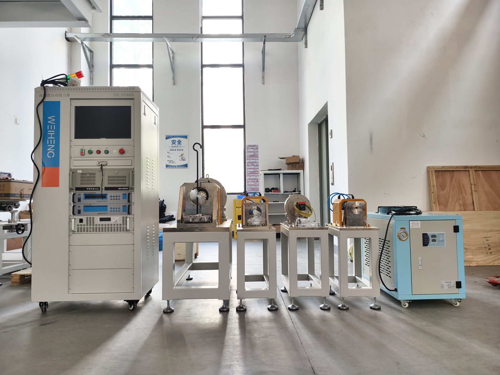
- The real equipment photograph confirms physical control, loading, fixture and cooling elements. It does not prove a particular envelope, quadrant, response, accuracy or acceptance result.
Common Mistakes
What causes an undersized or mismatched system?
- Selecting only by rated power and ignoring the torque required at low speed
- Using peak torque as though it were a continuous thermal rating
- Ignoring maximum speed, overspeed margin, direction, and the complete operating quadrant
- Leaving the motor inertia, coupling, alignment, and fixture design until late in the project
- Requesting fast transient tests without defining the target sequence and measurement timing
- Comparing loading units without comparing the complete bench, controls, sensors, safety, and software
For the measurement side of the project, continue with the motor torque-speed and efficiency testing guide.
FAQ
Motor Dynamometer Selection Questions
How do I size a motor dynamometer?
Start with the full torque-speed envelope, then verify continuous and peak power, duty duration, maximum speed, dynamics, cooling, mechanical interface, and control requirements. A single rated power value is not enough.
Should I select a dynamometer by torque or power?
Both matter. Torque usually governs low-speed loading, while power becomes critical as speed rises. The selected unit must cover the required operating points without exceeding torque, speed, power, or thermal limits.
Can peak torque be used continuously?
Not unless the proposed dynamometer is specifically rated for that condition. Peak capability normally has a defined duration and recovery condition, so the actual test cycle must be reviewed.
Why does inertia matter in motor dynamometer selection?
Combined inertia affects acceleration, deceleration, dynamic response, and how closely the bench can reproduce a requested transient sequence.
Can one dynamometer test several motor models?
It may be possible when their envelopes, interfaces, cooling, controls, and test workflows are compatible. Adjustable fixtures or planned changeover hardware may be required.
What is different when selecting a dynamometer for a PMSM?
The selection should include the PMSM and inverter operating envelope, field-weakening or maximum-speed region, motoring and generating quadrants, DC-link and energy-flow behavior, required low-speed tests, cooling, control interfaces, and the exact test sequence. The motor label alone is not sufficient.
Should an EV team build or buy a motor dynamometer test bench?
Build-versus-buy should be decided from engineering ownership, schedule, safety, integration, measurement traceability, acceptance, and lifecycle support rather than hardware price alone. An internal build can fit exploratory work when the team owns every subsystem and accepts iteration. A supplied system fits when a defined delivery, integration, documentation, and acceptance boundary is required.