
Direct Answer
What should an EV motor efficiency-map test system include?
An EV motor efficiency-map test system should combine a loading machine that covers the required motoring and generating quadrants, torque and speed measurement, defined DC or AC electrical-power boundaries, synchronized acquisition, inverter control, cooling and temperature conditioning, safety interlocks, and software that validates each torque-speed point before calculating and exporting the map. The procedure must define the DUT boundary, direction of power flow, stabilization rule, averaging window, invalid-point logic, and report fields.
The system architecture depends on whether the result is for the motor, inverter, their combination, or a wider drive system. That boundary must be fixed before channels, calculations, and acceptance criteria are selected.
Efficiency-Map Architecture
Seven connected steps from test objective to traceable map.
| System step | What the proposal and procedure should define |
|---|---|
| 1. Define the DUT boundary | State whether the result covers the motor alone, inverter alone, motor-plus-inverter system, or a wider power-drive system. Identify the electrical measurement plane and mechanical shaft plane. |
| 2. Define the operating grid | Provide motoring and generating torque-speed points, direction, controller mode, voltage condition, point order, ramps, dwell, repeat count, and stop limits. |
| 3. Control load and speed | Use a loading machine and control architecture that can reach and hold every required point within its verified torque-speed-time and thermal envelope. |
| 4. Measure both power paths | Record torque and speed at the mechanical boundary and the required DC or AC voltage, current, and power at the declared electrical boundary. |
| 5. Control thermal state | Define coolant medium, inlet temperature, flow, pressure, ambient condition, component temperatures, warm-up, stabilization, and protection thresholds. |
| 6. Synchronize and validate | Align mechanical, electrical, thermal, controller, and status data; apply the agreed settling, averaging, invalid-point, alarm, and retest rules. |
| 7. Calculate and export | Apply the agreed sign convention and efficiency definition, retain raw and processed values, and export the point table, map, conditions, exceptions, and judgment record. |
Point-Level Evidence
What should be retained for every torque-speed point?
A trustworthy efficiency map remains auditable back to its individual operating points. Request the following fields in the data and report design instead of accepting only a finished contour graphic.
| Record group | Minimum traceable content |
|---|---|
| Identity | DUT serial or revision, inverter/controller version, software recipe, operator, date, and test-run identifier |
| Requested point | Commanded torque, speed, direction or quadrant, controller mode, DC-link or supply condition, and sequence position |
| Measured mechanical values | Torque, speed, calculated mechanical power, measurement range, validity state, and applicable calibration reference |
| Measured electrical values | Declared DC or AC boundary, voltage, current, active power, acquisition mode, and validity state |
| Thermal conditions | Ambient, coolant inlet/outlet conditions, component temperatures, warm-up state, and stabilization result |
| Timing and quality | Arrival time, dwell, settling rule, averaging window, synchronization status, alarms, rejected samples, and repeat status |
| Calculated result | Efficiency definition, sign convention, formula version, point result, loss result when required, and processing version |
| Evidence output | Raw-data reference, processed point table, contour-map version, invalid or missing points, tolerance, reviewer, and approval state |
Test Scope
Six groups for an actionable EV motor test plan.
Basic operating checks
Direction, no-load behavior, speed stability, signal plausibility, cooling status, controller communication, and safe operation before loaded testing.
Torque-speed performance
Controlled operating points or sweeps establish torque, speed, power, current, voltage, and the usable operating envelope.
Efficiency evaluation
Synchronized mechanical and electrical measurements support point efficiency, efficiency maps, and comparison across control settings or motor revisions.
Thermal performance
Temperature channels, coolant conditions, load duration, stabilization criteria, and protection limits are defined for temperature-rise and continuous-duty work.
Dynamic and drive-cycle tests
Ramps, acceleration and deceleration, reversal, load steps, regenerative operation, and repeated application cycles are configured when required by the project.
Durability and reliability
Repeated cycles or endurance sequences combine defined load, speed, cooling, protection, alarms, data logging, and stop conditions.
Plan Review
Which tests, parameters, and pitfalls should an EV powertrain dynamometer plan cover?
A useful EV powertrain test plan connects each engineering decision to a defined DUT boundary, torque-speed-time condition, electrical and mechanical measurement plane, thermal state, dynamic sequence, evidence output, and acceptance method. The following gaps should be closed before the team compares a dynamometer or complete test-system proposal.
| Planning risk | Typical gap | Required correction |
|---|---|---|
| Undefined system boundary | A test list says efficiency or power without stating whether the DUT is the motor, inverter, combined drive, or complete power-drive system. | Declare the electrical and mechanical measurement planes, included components, direction of power flow, and result label before selecting channels. |
| Ratings without a torque-speed-time envelope | Peak torque, maximum speed, and maximum power are treated as if they occur together or continuously. | Provide every required motoring and generating point, duration, ramp, repetition, cooling state, and overload or stop rule. |
| A finished map without point evidence | The plan requests a contour image but omits raw-data references, point validity, stabilization, averaging, rejected points, and calculation version. | Define the point table, raw and processed records, synchronization status, invalid-point logic, retest rule, and map version. |
| Thermal state left uncontrolled | Coolant, ambient, warm-up, dwell, and component temperatures are not tied to each test result. | Specify coolant medium, inlet conditions, flow, pressure, ambient, stabilization rule, temperatures, and protection thresholds. |
| Dynamic cycle without timing definitions | A drive cycle or transient request omits command source, ramp, inertia, trigger, sampling, delay, settling, stop, and repeat conditions. | Separate command timing, mechanical response, measurement timing, control state, protection behavior, and review criteria. |
| Acceptance added after configuration | Tolerance, witness, invalid-run handling, reports, supplied test articles, and sign-off are discussed only after hardware selection. | Carry requirement IDs, evidence outputs, exceptions, responsibilities, and verification stages from RFQ through FAT or site review. |
Use the EV motor test bench RFQ checklist to separate confirmed inputs, targets, open items, supplier proposals, and exclusions before requesting a configuration.
Project Stage
Match the test items to the decision being made.
| R&D characterization | Torque-speed curves, efficiency maps, thermal behavior, controller calibration support, dynamic response, and comparative development data. |
|---|---|
| Design validation | Defined operating points, overload or limit conditions within the approved procedure, drive cycles, durability, protection behavior, and traceable reports. |
| Quality control | Repeatable checkpoints, model identification, controlled sequences, tolerances, trend data, and clear operator results. |
| Production or EOL | Short automated sequences, barcode or serial traceability when required, pass/fail logic, report storage, and safe fixture changeover. |
For the complete equipment architecture, see the EV motor test system. For measurement logic, read the torque-speed and efficiency testing guide.
Reference Scope
Choose the test method before claiming standards alignment.
ISO 21782-1:2023 defines general conditions for electric-propulsion components and combinations; ISO 21782-2:2019 covers performance testing of the motor system, while ISO 21782-3:2019 covers the motor and inverter. IEC 60034-2-3:2024 addresses losses and efficiency of converter-fed motors, and IEC 61800-9-2:2023 addresses energy-efficiency indicators for drive-system elements.
These references demonstrate why the DUT boundary and procedure matter. Weiheng does not claim compliance merely because a standard is named on this page; the applicable edition, clauses, instrumentation, conditions, calculations, and acceptance evidence must be agreed for the project.
Limits and Evidence Boundaries
What this guide and photograph do not prove.
- Motor efficiency, inverter efficiency, motor-system efficiency, and complete power-drive-system efficiency are different results. The declared measurement boundaries must match the reported label.
- A colored contour plot is not sufficient evidence by itself. The point table, raw-data reference, conditions, validity rules, calculation version, and rejected points should remain traceable.
- The required grid, stabilization rule, averaging window, uncertainty, tolerance, and applicable standard are project decisions. This guide does not impose universal values.
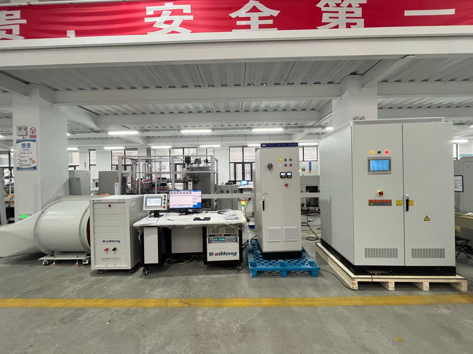
- The real equipment photograph confirms physical integration of loading, control, power, cooling, and operator elements. It does not prove efficiency, accuracy, synchronization, standard compliance, or a project acceptance result.
Before Quotation
Inputs needed to turn the test list into a system.
- Motor type, rated and peak torque, power, base speed, and maximum speed
- DC bus or AC supply information, inverter or controller model, and communication protocol
- Cooling medium, flow, temperature range, pressure limits, and stabilization requirement
- Required operating points, efficiency-map grid, drive cycle, or internal test procedure
- Temperature, vibration, electrical, environmental, or other optional measurement channels
- Shaft and flange drawing, mounting direction, coupling, fixture, guard, and service access
- Report fields, sampling needs, units, language, traceability, and pass/fail rules
- Laboratory or production environment, available utilities, test volume, and operator workflow
FAQ
EV Motor Testing Questions
What are the main EV motor test items?
Common groups include basic operation, torque-speed performance, efficiency, thermal behavior, dynamic or drive-cycle response, regenerative operation when applicable, durability, protection checks, and repeatable report output.
What is needed for an EV motor efficiency map?
The project must define the speed-torque grid, stabilization method, electrical and mechanical measurement channels, cooling condition, controller settings, data handling, and report format.
Can the motor and inverter be tested together?
Yes, when the system architecture, voltage platform, communications, safety, cooling, and measurement boundaries are defined. The proposal should state whether the objective is motor-only, inverter-only, or combined electric-drive performance.
Are R&D and end-of-line EV motor tests the same?
No. R&D usually needs broader characterization and flexible sequences, while EOL normally prioritizes short repeatable checks, traceability, pass/fail logic, and production workflow.
What should an EV motor test report include?
Typical fields include test identity, operating conditions, commanded and measured values, torque, speed, power, electrical data, temperatures, alarms, calculated results, curves, and the agreed judgment criteria.
Is motor efficiency the same as motor-system efficiency?
No. The reported result changes with the measurement boundary. A motor-only result, an inverter result, and a combined motor-system result must identify different electrical and mechanical input-output planes.
Which pitfalls should an EV powertrain dynamometer test plan avoid?
Avoid an undefined DUT boundary, isolated headline ratings, uncontrolled thermal conditions, a finished map without point-level evidence, dynamic cycles without timing definitions, and acceptance rules added after configuration. Resolve these items in the test plan before comparing hardware.