
Direct Answer
How should robot joint position accuracy and repeatability be tested?
Test robot joint position accuracy by comparing each commanded target with the attained angle at the declared output measurement plane. Test repeatability by repeating the same target, approach, load, controller state, temperature, and stabilization rule, then reporting the individual attained positions and their variation.
Use an independent output reference when the engineering decision concerns the complete joint output. Keep motor-side feedback, output-side feedback, external reference, approach direction, external torque, fixture behavior, drive settings, and thermal condition in the record. Accuracy, repeatability, bidirectional behavior, backlash, stiffness, and dynamic response are related but different results.
Metric Boundary
Separate closeness to target from repeated-position variation.
| Metric | Engineering meaning | Required record | Interpretation boundary |
|---|---|---|---|
| Position accuracy | Difference between the declared target and the attained output position under the stated reference and conditions | Target, attained output angle, signed and absolute error, direction, load, position, temperature, controller state, and validity | Do not substitute repeated clustering for closeness to the reference |
| Position repeatability | Variation among repeated attained output positions when the declared target and conditions are repeated | Individual attained positions, center or stated statistic, spread, direction, load, position, temperature, cycles, and invalid runs | Do not report repeatability as absolute accuracy |
| Bidirectional positioning | Difference caused by approaching the same target from opposite directions or histories | Positive and negative approach results, reversal history, preload, holding state, torque, angle, and temperature | Keep this result separate from a full backlash or lost-motion loop |
| Loaded position holding | Output position behavior while the powered joint holds a declared command under a stated external torque | Command, motor-side and output-side angle, output torque, supply, current limit, control mode, dwell, drift, and temperature | A loaded hold is not a dynamic-response result or a universal stiffness value |
Measurement Boundary
Name the DUT, command, feedback, external reference, fixture, and operating state.
| Boundary | What the project should freeze |
|---|---|
| DUT | State whether the result covers the reducer, an unpowered actuator, or the complete powered joint including motor, reducer, encoder, drive, brake, firmware, compensation, housing, bearings, and output interface. |
| Command and feedback | Record the command source, motor-side encoder, output-side encoder, drive state, calibration or compensation state, resolution, units, sign convention, and software versions used in the decision. |
| External reference | Name the independent output-angle reference, its mounting and measurement plane, zero/alignment method, traceability or verification status, uncertainty input, and synchronization with the joint data. |
| Mechanical path | Document the output flange, adapter, lever or fixture, coupling, fasteners, alignment, runout, support structure, guarding, reference mounting, and any compliance or movement that can affect the result. |
| Operating condition | Declare target positions, approach direction and history, speed, acceleration, dwell and stabilization rule, external torque or inertia, orientation, supply, current limit, control mode, temperature, and preconditioning. |
Test Workflow
Seven steps from a declared target to a reviewable position result.
| Step | Required definition and evidence |
|---|---|
| 1. Freeze the decision | Choose whether the project needs accuracy, repeatability, bidirectional positioning, loaded hold, or a defined combination. Do not begin with an unlabeled 'precision' value. |
| 2. Name the output boundary | Identify the complete DUT and the physical output plane. Record what the motor-side feedback represents and what the independent output reference measures. |
| 3. Establish references | Verify identity, revisions, mounting, alignment, zero, reference status, controller state, safety limits, data channels, time base, units, sign conventions, and invalid-run rules. |
| 4. Define the target matrix | Select positions across the required working region, positive and negative approach directions, repeated cycles, loads, orientations, thermal states, speeds, dwell, and preconditioning that match the engineering decision. |
| 5. Execute and synchronize | Command each target using the approved approach, allow the stated stabilization condition, record the independent output angle with command, internal feedback, torque, current, temperature, alarms, and fixture observations. |
| 6. Separate the calculations | Calculate target error and repeated-position variation using the approved definitions. Keep bidirectional results, drift, invalid runs, outliers, and retests visible instead of compressing them into one number. |
| 7. Review evidence | Retain raw records, method and calculation versions, target matrix, environmental and controller conditions, fixture/reference evidence, uncertainty inputs, exceptions, reviewer, and acceptance decision. |
Weiheng Error-Separation Plan v1.0
Keep raw error, temperature drift, compensation, and source estimates as separate results.
Temperature compensation and encoder or reducer error separation require independent reference planes and controlled thermal, direction, load, and position states. Weiheng retains raw uncompensated results, compensation-model version, and compensated outputs separately, then compares motor-side feedback, output reference, torque, temperature, and controller state.
| Output | Required definition | Do not relabel it as |
|---|---|---|
| Raw position or angle error | Command or independent reference minus measured output result before compensation | Not compensated accuracy |
| Temperature drift | Change in a named metric across controlled thermal state and time | Not all long-term drift or wear |
| Compensation effect | Raw versus compensated result with a declared model version and independent evaluation set | Not proof that the physical source was removed |
| Error-source estimate | Bounded contribution supported by independent references or controlled intervention | Not unique root cause from correlation alone |
Freeze hardware, fixture, controller, firmware, calibration, processing, and model versions; separate fitting data from independent validation data; preserve compensation-off and compensation-on records; and state the valid temperature, position, load, speed, direction, firmware, and assembly domain. When independent evidence cannot separate two candidate sources, record not identifiable with current evidence rather than assigning a root cause.
Use the Thermal and Endurance Test Guide to define thermal state and duty cycle, and the Backlash and Stiffness Test Guide for bidirectional mechanical metrics. This plan does not claim a Weiheng accuracy, drift, compensation result, or diagnostic capability.
Intent Routing
Use the method page that matches the engineering decision.
| Decision | What it measures or controls | Correct route |
|---|---|---|
| Robot joint position accuracy and repeatability | Steady attained output position relative to a stated target and the spread across repeated approaches | This page |
| Backlash, lost motion, and torsional stiffness | Bidirectional torque-angle mechanical behavior and declared constraint boundary | Open guide |
| Servo dynamic response | Delay, rise, peak, overshoot, settling, tracking, and oscillation on a synchronized time base | Open guide |
| Robot joint EOL | Short every-unit production sequence, recipe control, pass/fail/invalid states, traceability, and disposition | Open guide |
| Complete robot pose or path performance | Tool-center-point position and orientation across the assembled robot kinematic chain | Outside this component-level page |
Required Record
Keep the conditions behind every position result.
- DUT model, serial/revision, integrated components, firmware, parameter and compensation versions, and mounting orientation
- Command target, approach direction and history, motor-side feedback, output-side feedback, independent reference, measurement planes, units, and sign conventions
- Target positions, speed, acceleration, dwell, stabilization rule, external torque or inertia, control mode, current limit, supply, brake state, and safety limits
- Fixture, adapter, lever, coupling, fasteners, alignment, runout, support, reference mounting, observed movement, and compliance treatment
- Ambient, housing, motor, reducer or other agreed temperatures plus preconditioning and thermal-state definition
- Synchronized raw records, individual attained positions, target errors, repeated-run distribution, bidirectional difference, drift, invalid runs, retests, and calculation version
- Reference verification or traceability status, resolution, uncertainty inputs, data validity checks, reviewer, acceptance method, and approved limits
Weiheng Test-System Context
Connect the complete joint, output reference, loading, control, and report workflow.
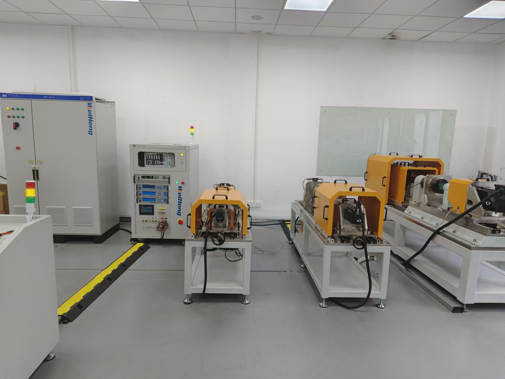
Weiheng can configure robot joint test platforms around the declared joint boundary, output interface, loading or holding condition, motor-side and output-side feedback, independent angle reference, fixture, control state, synchronized channels, safety, and report workflow. The method and acceptance limits remain project-specific.
Start with the Robot Joint Module Test Bench Configuration Guide when the DUT boundary and system architecture are not yet frozen. Use the Backlash and Stiffness Test Guide for bidirectional torque-angle mechanical metrics, the Thermal and Endurance Test Guide for hot-cold and duty-cycle evidence, or the Robot Joint EOL Guide for every-unit production release.
Reference Boundaries
Use public references for terminology without overstating component scope.
ISO 9283:1998 identifies position and path performance criteria for manipulating industrial robots. It supports the distinction between accuracy and repeatability, but it does not automatically certify a standalone joint module or turn a component result into a complete robot tool-center-point result.
Renishaw's public robot ballbar test explanation distinguishes global-joint and single-joint repeatability checks for assembled robots. Its equipment, methods, and results are not Weiheng specifications; this page uses the source only to clarify why the measurement object and boundary must be named.
FAQ
Robot Joint Position Accuracy and Repeatability Questions
Are robot joint position accuracy and repeatability the same?
No. Position accuracy describes how close the attained output position is to the declared reference target. Position repeatability describes the variation among repeated attained positions under the same declared conditions. A joint can repeat consistently while remaining offset from the target.
Can a motor-side encoder prove robot joint output accuracy?
Not by itself. The motor-side reading may not include reducer transmission effects, compliance, output-interface motion, compensation behavior, or fixture influence. Name the measurement plane and use an independent output reference when the decision concerns the complete joint output.
Should the joint approach the target from both directions?
Use both directions when reversal history matters to the decision. Record direction, preload, controller state, load, position, temperature, and the calculation separately. A bidirectional position check is not automatically the same as a complete backlash or lost-motion test.
Is robot joint position testing the same as ISO 9283 robot pose testing?
No. ISO 9283 addresses performance criteria and test methods for manipulating industrial robots. A component-level joint test has a different DUT and measurement boundary. The standard can support terminology, but it does not automatically certify a standalone joint module or make its result a complete robot TCP result.
What should be sent for a robot joint position test proposal?
Send the joint drawing and revisions, integrated components, output interface, command and encoder architecture, reference method, target positions, approach directions, loads, motion profile, control state, temperature conditions, repeated-cycle plan, required records, acceptance method, site conditions, and target country.