
Direct Answer
How is servo motor dynamic response measured?
Measure servo motor dynamic response by applying a precisely defined torque, speed, or position command under a stated load and inertia, then recording command and measured response on one synchronized time base. Report delay, rise time, peak and overshoot, settling band and time, steady-state or tracking error, oscillation, current and thermal state. Define thresholds, filtering, controller settings, fixture, repeat count, invalid runs, and whether bandwidth comes from a separate frequency-response test.
The metric belongs to the complete tested path, not the motor nameplate alone. Changing the drive, tuning, filter, coupling, fixture, inertia, load, voltage, temperature, limit, or calculation definition can change the result.
Measurement Workflow
Seven steps from defined stimulus to signed response result.
| Step | Required definition and evidence |
|---|---|
| 1. Freeze the tested system | Identify the servo motor, drive, controller, feedback, firmware, tuning gains, filters, current/torque limits, power supply, fixture, coupling, load, reflected inertia, cooling, and mounting included in the result. |
| 2. Define the stimulus | State whether the command is torque, speed, position, disturbance load, or frequency injection; record the initial value, final value or amplitude, direction, slope, trigger, repetition, and stop condition. |
| 3. Define the operating condition | Set the preload or operating speed, external load and inertia, control mode, temperature state, voltage condition, travel limit, acceleration limit, and any saturation expected during the test. |
| 4. Synchronize command and response | Record the command at its source and the measured output on one time base, together with torque, speed, position, current, voltage, temperature, controller state, limits, and alarms required by the question. |
| 5. Validate the run | Apply declared trigger alignment, sample timing, filtering, smoothing, invalid-sample, saturation, alarm, interruption, and repeat rules before calculating response metrics. |
| 6. Calculate named metrics | Use explicit thresholds, windows, reference values, units, sign conventions, and formulas for delay, rise, peak, overshoot, settling, steady-state or tracking error, oscillation, and frequency response. |
| 7. Compare and accept | Retain command–measured curves and raw-data references; compare repeated runs under the same setup; report exceptions, retests, tolerance, reviewer, and sign-off against the intended application. |
Metric Definitions
Do not report “response time” without naming the metric.
| Metric | Meaning | What must accompany the result |
|---|---|---|
| Delay | Time between a defined command event and a defined response event | Command/response thresholds, trigger alignment, channels, filters and interpolation |
| Rise time | Time for the response to move between declared lower and upper fractions or levels | Initial/final reference, threshold pair, direction, load, saturation and whether the response crosses each threshold once or repeatedly |
| Peak and overshoot | Maximum response and any amount beyond the declared final or reference value | Step amplitude, final-value method, sign, evaluation window, clipping and percentage denominator |
| Settling time | Time after which the response enters and remains inside a declared error band | Band width, final/reference value, required stay duration, noise handling, observation window and restart rule |
| Steady-state error | Difference between command and response over a declared stable window | Window, statistic, units, bias/offset treatment, load and thermal state |
| Tracking error | Difference between command and response during a defined trajectory or cycle | Profile, phase alignment, pointwise/peak/RMS or other statistic, direction, load and included intervals |
| Oscillation or resonance | Residual motion, ringing, spectral peak or response amplification under a defined stimulus | Excitation, sensor/channel, window, frequency resolution, controller/filter state, fixture and acceptance rule |
| Bandwidth and stability margins | Frequency-domain behavior of a specified open-loop or closed-loop input-output path | Injection point, response point, sweep, amplitude, operating condition, gain/phase convention and bandwidth/margin criterion |
Configuration Logic
Six areas to define before building the test sequence.
Torque response
Define the commanded torque change, operating speed, loading condition, duration, and required data fields before selecting a sequence.
Speed response
Confirm the speed target, acceleration or deceleration profile, load condition, overshoot or settling criteria where applicable, and report need.
Start-stop and reversal
Specify start-stop frequency, forward/reverse operation, load profile, duty cycle, and the safety or endurance requirements around the cycle.
Synchronized channels
Torque and speed can be aligned with voltage, current, power, temperature, drive-related, position-related, vibration, and custom signals when required.
Mechanical interface
The motor shaft, flange, coupling, alignment, fixture, guarding, cooling, and installation direction must fit the dynamic operating condition.
Workflow and report
R&D validation, laboratory work, production QC, and EOL testing require different sequence logic, operator flow, traceability, and pass/fail rules.
Test-Bench Scope
Dynamic performance is a system question, not only a motor question.
Servo response depends on the motor, drive, controller settings, load, coupling, fixture, thermal condition, control mode, and the measurement/report method. The test requirement should state which of those elements are fixed, supplied by the buyer, or part of the proposed test platform.
See the Servo Motor Test System for the broader system architecture, and the Motor Torque-Speed and Efficiency Testing Guide for controlled loading and synchronized measurement basics.
Reference Boundaries
Time-domain and frequency-domain evidence answer different questions.
MathWorks' step-response documentation separates rise time, settling time, overshoot, peak, and peak time, and shows that thresholds and the final-value definition affect the result. Yaskawa's servo-system manual explains that controller, servodrive, servomotor, encoder, mechanical rigidity, load inertia, loop gains, and filters all influence response.
Kollmorgen's servo stability guidance distinguishes bandwidth, gain margin, phase margin, stiffness, inertia, and resonance, while its frequency-response tooling distinguishes open-loop and closed-loop measurements. These sources support definitions and test design; their product-specific examples are not Weiheng performance evidence.
Limits and Evidence Boundaries
What this guide and equipment photograph do not prove.
- There is no meaningful universal servo response time without a named command-response path, step or trajectory, load and inertia, control settings, thresholds, filters, voltage, thermal state, and limit or saturation status.
- Delay, rise time, peak time, overshoot, settling time, steady-state error, tracking error, bandwidth, gain margin, and phase margin are different metrics. A page or report must not rename one as another.
- Drive current or commanded torque is not automatically measured shaft torque. The torque boundary, sensor or estimation method, range, calibration status, synchronization, and uncertainty need separate evidence.
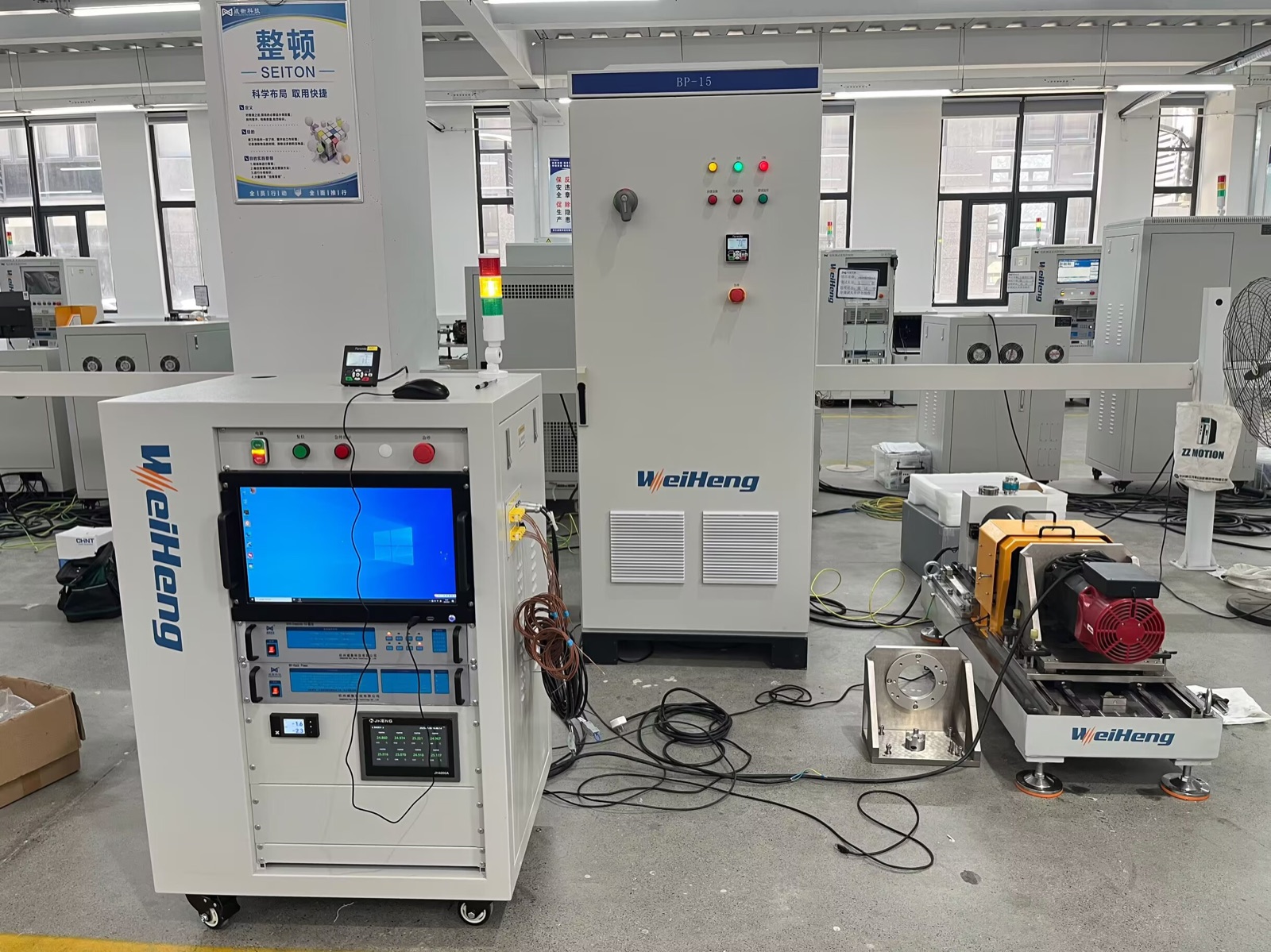
- The original Weiheng photograph verifies physical loading, control, measurement, fixture, and power equipment. It does not prove a response time, bandwidth, sampling rate, accuracy, stability margin, or acceptance result.
Before Quotation
Inputs that make a servo response-test request actionable.
- Servo motor rated power, rated torque, peak torque, rated speed, and maximum speed
- Drive or controller model, interface, communication requirement, and power platform
- Required torque step, speed step, acceleration, deceleration, start-stop, reversal, overload, or duty-cycle profile
- Motor drawing, shaft and flange details, coupling, mounting orientation, fixture, guard, and cooling requirement
- Required channels and outputs: torque, speed, electrical values, temperature, position-related signals, vibration, curves, raw data, or reports
- R&D, laboratory, quality-control, or EOL use case; expected test quantity and traceability requirement
For broader system inputs, use the Custom Motor Test Bench Configuration Guide.
FAQ
Servo Dynamic Response Test Questions
What is a servo motor dynamic response test?
A servo motor dynamic response test evaluates behavior during defined changes in torque, speed, direction, load, or operating sequence. A complete test workflow combines controlled loading, synchronized measurement, fixture design, safety, data acquisition, and reporting around the engineering question.
What is needed to test servo torque response?
The requirement should identify the motor and drive, torque range, speed range, target torque change or load profile, duration, required measurement channels, mechanical interface, and the expected curve, report, or acceptance workflow.
Can the same servo test bench support R&D and production QC?
It can be discussed, but R&D validation and production QC normally need different sequences, cycle time, operator interaction, traceability, pass/fail logic, and report fields. These should be defined before system configuration.
Can Weiheng configure dynamic servo test software in English?
English interface, automatic sequences, curve display, data storage, pass/fail logic, and report templates can be discussed against the required workflow and data fields.
Which metrics describe servo step response?
Common metrics include delay, rise time, peak, overshoot, settling time, steady-state error, and oscillation. Each needs declared thresholds, reference values, evaluation windows, filtering, load, inertia, controller settings, and units.
Is servo bandwidth the same as response time or sampling rate?
No. Bandwidth is a frequency-domain property of a specified input-output path. Response time is a time-domain result under a defined stimulus, while sampling rate describes data collection. None can substitute for the others without a validated relationship and method.