Robot Reducer Manufacturers
Build a declared input-output test boundary for precision reducers used in robot joints, actuators, and motion systems.
 Start a Project
Robot and Precision Gearbox Testing
Weiheng configures custom reducer test systems and gearbox test benches around the reducer DUT, input drive, output loading, mechanical interfaces, measurements, software, safety, and required evidence.
Use this route when the device under test is the reducer itself. Complete powered robot joints and motor-drive assemblies follow different system boundaries.
Direct Answer
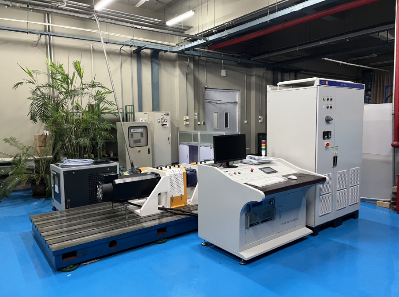
A reducer test system drives the gearbox input, applies a controlled load at the output, holds the DUT in a declared fixture, and records the required input-output torque, speed, angle, temperature, vibration, noise, or other project channels. The complete bench coordinates drive and load machines, couplings and guards, synchronized measurement, control and safety, calculations, raw data, curves, reports, and the approved R&D or production workflow.
Application Fit
Compatibility and final test coverage depend on the delivered reducer, interfaces, operating envelope, fixture, method, and required evidence.
Build a declared input-output test boundary for precision reducers used in robot joints, actuators, and motion systems.
Configure fixtures, input drive, output loading, angle references, thermal monitoring, and project-specific performance methods around the delivered reducer.
Plan low-speed output loading, torque transmission, temperature, endurance, vibration, noise, and production checks around the actual interfaces and method.
Use a flexible platform for engineering characterization, comparison, durability, quality control, or production evidence.
Separate reducer-only behavior from the motor, drive, encoder, housing, brake, firmware, and complete powered-joint result.
System Boundary
| System group | Project definition |
|---|---|
| Input drive | Drive motor, control mode, speed and torque region, direction, ramps, cycle, inertia, coupling, and input-side measurement plane |
| Reducer DUT | Reducer type, model, ratio, drawing revision, shaft/flange interfaces, mounting, orientation, lubricant state, backlash or preload condition, and allowable loads |
| Output loading | Loading machine or brake, output torque-speed-time envelope, direction, dwell, reversal, endurance sequence, cooling, and response requirement |
| Mechanical fixture | Base, adapters, couplings, alignment, constraint, bearing support, fasteners, guards, service access, and fixture-compliance treatment |
| Measurement | Input and output torque, speed, angle or position, temperature, vibration, noise, electrical values, time synchronization, ranges, and project-specific uncertainty inputs |
| Control and evidence | Sequence control, limits, interlocks, emergency stop, alarms, invalid-run rules, raw data, calculations, curves, reports, traceability, and review workflow |
Test Objectives
The final matrix follows the reducer, decision, standard or customer method, available sample, and approved acceptance logic.
Define the input and output angle or speed planes, direction, load state, calculation method, and comparison boundary.
Measure synchronized input and output torque and speed under declared lubrication, temperature, load, direction, and calculation conditions.
Use the named mechanical boundary, bidirectional torque-angle record, fixture treatment, and metric definition rather than one unlabeled value.
Translate the application into a torque-speed-time cycle with mounting, lubrication, cooling, temperature channels, checkpoints, interruption rules, and before-after evidence.
Declare operating point, sensor or microphone location, fixture, ambient condition, sampling, analysis method, and acceptance owner before comparing results.
Select only the repeatable checks needed for the production decision, with fixture control, golden-reference or MSA rules where approved, traceability, and exception handling.
Use the Backlash, Lost Motion and Stiffness Test Guide for mechanical metric definitions, the Torque-Speed and Efficiency Testing Guide for synchronized power boundaries, and the Robot Joint Thermal and Endurance Test Guide for duty-cycle and checkpoint planning.
System Architecture
Selected around the complete input-output torque, speed, power, direction, duration, inertia, dynamic, cooling, and endurance requirement.
Input and output measurement planes can be planned for ratio, transmission, efficiency, running, and comparison evidence.
Project-specific angle references, input locks, output loading, and fixture treatment can support declared backlash, lost-motion, transmission-error, or stiffness methods.
Temperature, vibration, noise, lubricant, ambient, and other channels can be integrated when their locations and decision methods are defined.
Custom adapters, shafts, couplings, bases, supports, alignment, guards, access, and changeover can follow the reducer drawing and workflow.
Automatic sequences, synchronized records, limits, interlocks, alarms, invalid-run handling, curves, comparison, traceability, and report output can be configured.
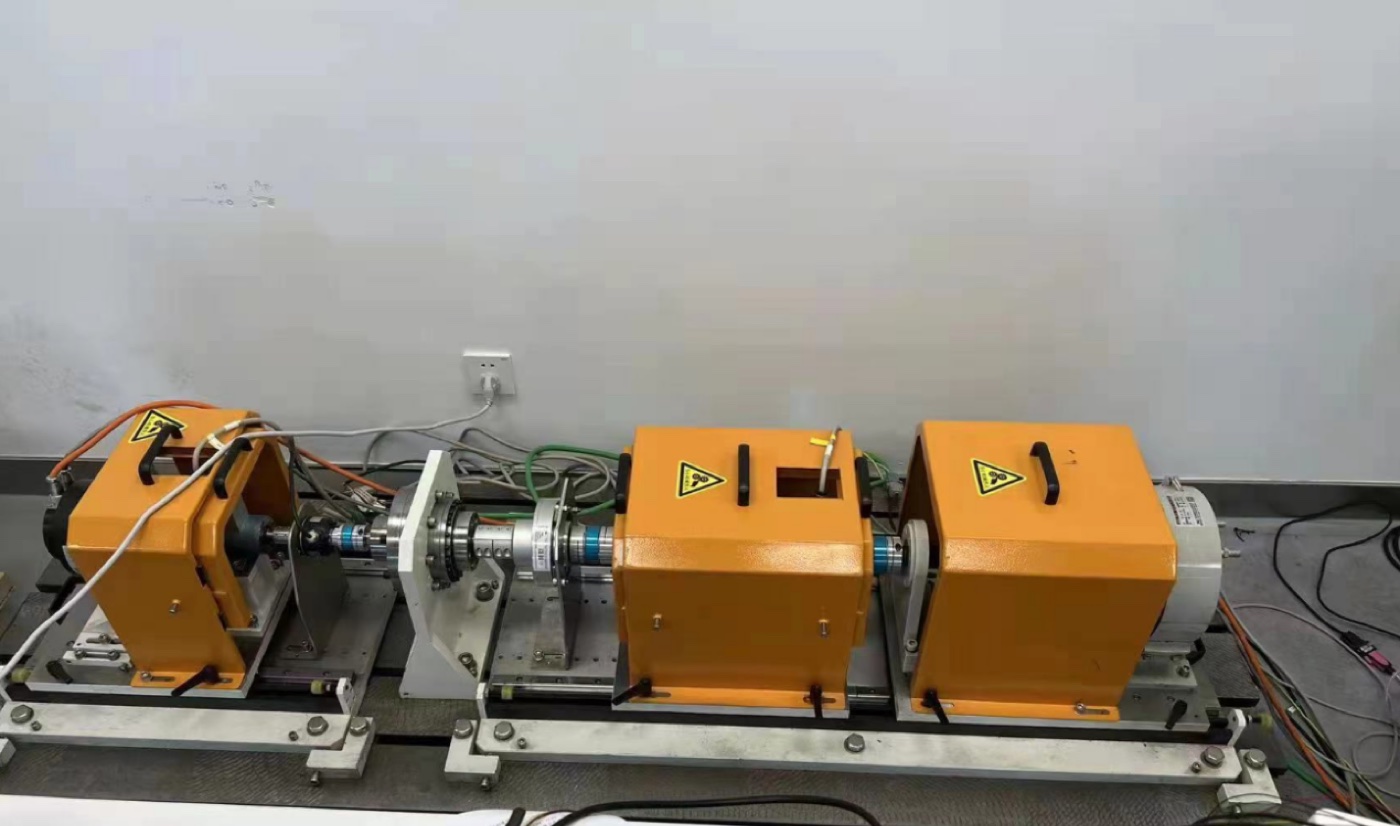
Physical Integration Evidence
This original Weiheng photograph shows a coaxial mechanical path with drive or load equipment, coupling and sensor area, support fixture, guarded units, and an adjustable test base. It is visual context for system integration; actual test functions and results remain tied to the approved project configuration and records.
For complete powered actuators, continue to the Robot Joint Module Motor Test System.
Workflow Choice
| Workflow | Primary configuration need | Evidence output |
|---|---|---|
| R&D characterization | Flexible operating points, methods, sensor options, setup changes, investigation and engineering comparison | Configurable sequences, raw and processed data, exceptions, versions, curves, reviewer context |
| Validation and endurance | Approved duty cycles, thermal state, checkpoints, interruption/restart logic, inspections, and before-after reference methods | Cycle and event history, temperatures, alarms, periodic checks, deviations, disposition and final evidence |
| Incoming or quality control | Repeatable fixture, defined sample, limited checks, reference rules, calibration/MSA context, and controlled operator workflow | Traceable result, exceptions, retest link, setup identity, status and quality decision |
| Production EOL | Only the checks needed for the next process or shipment, with takt, automation, changeover, handling and line integration defined | Pass/fail context, serial/model/recipe, raw evidence as required, alarms, rework/retest and line records |
Before Quotation
Unknown values may be marked TBD, but assumptions, responsibilities, and the stage for resolving them should remain visible.
Use the Robot Joint Module Test Bench Configuration Guide when the project may expand from the reducer to the complete joint, and the Motor Test Data and Acceptance Planning Guide for raw data, calculations, exceptions, reports, and sign-off planning.
FAQ
A reducer test system is a complete bench that drives the reducer input, applies a controlled output load, holds the reducer in a declared fixture, measures the required input-output mechanical and optional thermal or NVH channels, and coordinates control, safety, data, calculations, and reports around an approved test method.
A reducer bench treats the gearbox or reducer as the DUT. A complete robot joint system may also include the motor, drive, encoder, brake, housing, firmware, cooling, and powered control behavior. Their results should not be compared without naming the boundary.
These reducer families can be discussed, but compatibility is project-specific. Weiheng reviews the delivered reducer, ratio, input-output interfaces, torque-speed-time envelope, mounting, lubrication, method, fixture, measurements, safety, and report requirements before proposing a configuration.
A custom platform can combine multiple functions when their loading, measurement planes, sensor ranges, fixtures, method, sequence, uncertainty inputs, safety, and acceptance rules are compatible. Each metric keeps its own definition and evidence boundary.
It can be planned for R&D, validation, quality control, or production, but those workflows need different flexibility, automation, cycle time, changeover, traceability, exception handling, and acceptance logic. The proposal should identify the primary workflow.
Send the reducer drawing and revision, type and ratio, input-output torque and speed regions, interfaces, mounting and lubrication, duty cycle, test items, measurement and accuracy needs, fixture responsibility, software and report requirements, site conditions, target country, and acceptance method.
Request a Proposal
Share the reducer type, ratio, drawing, input-output torque and speed regions, mounting, lubrication, duty cycle, test items, measurement and report needs, site conditions, target country, and acceptance method.