Steady-state points and sweeps
Use rated points, torque or speed sweeps, and synchronized electrical and mechanical data for performance curves and efficiency analysis.
Plan torque-speed and efficiency testing Request a Quote
 Controlled Motor Loading and Measurement
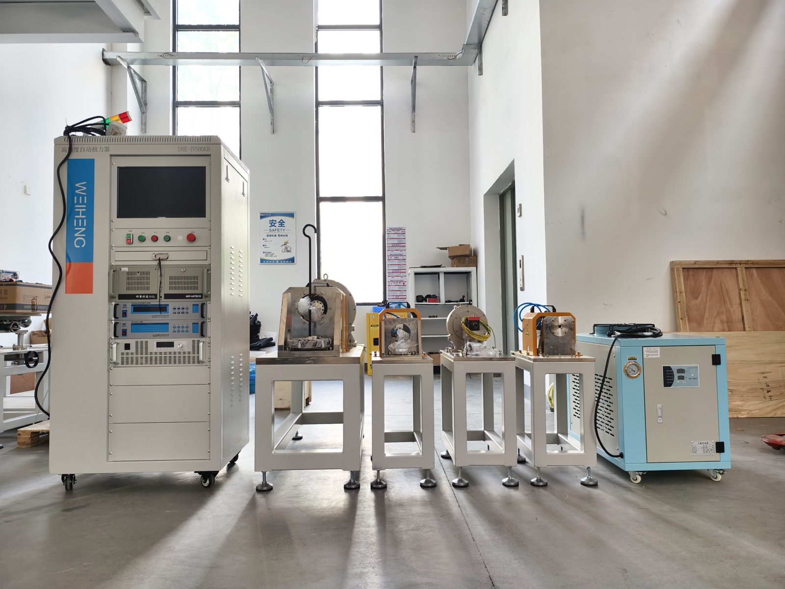
Weiheng configures custom dynamic test benches and motor dynamometer systems for controlled loading, torque-speed measurement, efficiency mapping, dynamic response, thermal tests, and durability validation.
The loading unit, measurement range, cooling, fixture, control mode, software, and safety functions are configured around your motor and test profile.
Direct Answer
A custom dynamic test bench applies a controlled mechanical load to a motor while measuring torque, speed, electrical input, mechanical output, efficiency, and thermal or response behavior. Unlike a loading unit selected from torque and speed alone, the complete system is configured around the motor envelope, load profile, inertia, control mode, measurement timing, fixtures, software, and acceptance method.
Test Route
The same peak torque value can lead to different configurations when the project requires steady points, fast steps, repeated cycles, or traceable acceptance data.
Use rated points, torque or speed sweeps, and synchronized electrical and mechanical data for performance curves and efficiency analysis.
Plan torque-speed and efficiency testingDefine the command profile, inertia, control loop, synchronized sampling, settling criteria, and review method before selecting hardware.
Plan dynamic response testingReview command, feedback, correction, actuator, mechanical load, acquisition, protection, and acceptance as one control chain.
Review closed-loop torque loadingCompare torque-speed envelope, peak duration, duty cycle, inertia, cooling, fixture, and acceptance requirements before requesting a proposal.
Compare motor dynamometer optionsDynamic Test Profiles
Some engineering teams use “dynamic test bench” to describe a motor dynamometer system configured for fast torque, speed, or load changes rather than only steady-state points.
Define the torque or speed step, ramp, cycle, settling time, overshoot, sampling rate, and repeatability target.
Evaluate the motor, dynamometer, coupling, fixture, and reflected inertia together before promising transient performance.
Coordinate the drive, loading control loop, synchronized acquisition, trigger logic, curve display, and report method.
For servo response methods, read the Servo Motor Dynamic Response Test Guide. For steady-state and sweep testing, use the Motor Torque-Speed and Efficiency Testing Guide.
AC Induction Motor Loading
A complete load test requires more than a brake or second motor. The loading method, mechanics, torque-speed measurement, electrical boundary, thermal condition, controls, acquisition, safety, and evidence output must all match the specified operating point and test decision.
| Controlled loading machine | Use a dynamometer or another verified loading method that covers the required torque-speed point, duration, direction, and thermal condition. A brake or coupled machine cannot be selected from rated power alone. |
|---|---|
| Mechanical interface | Define the induction-motor shaft, flange, mounting, coupling, alignment, guard, base, combined inertia, and safe service access. |
| Torque and speed measurement | Select declared measurement ranges and install the torque and speed channels within the same mechanical boundary used for the reported result. |
| Electrical and thermal measurement | Record the required voltage, current, input power, temperature, cooling, and ambient channels with the timing needed for the test decision. |
| Control, acquisition, and protection | Coordinate the motor drive, load control, synchronized acquisition, setpoint sequence, alarms, overspeed, overload, emergency stop, raw data, and report output. |
Start with the motor dynamometer selection guide, then use the closed-loop torque loading guide to define the command, feedback, protection, and acceptance chain.
Test Coverage
Test sequences and limits are confirmed against the motor, controller, standard, and validation plan.
System Architecture
Selected for rated and peak torque, maximum speed, power, duration, inertia, and dynamic response.
Measurement ranges and accuracy are matched to the motor and required test standard.
Voltage, current, input power, output power, and efficiency are synchronized with mechanical data.
Custom base, shaft alignment, coupling, guard, and fixture design for the device under test.
Closed-loop loading, emergency stop, overload protection, interlocks, and operating status control.
Automated sequences, curve display, data storage, report generation, and optional English workflow customization.
Selection Inputs
| Motor under test | Motor type, rated power, rated torque, peak torque, rated speed, and maximum speed |
|---|---|
| Load profile | Steady-state points, ramp loading, speed sweep, torque sweep, transient, or endurance cycle |
| Operating mode | Torque control, speed control, forward/reverse operation, and project-specific modes |
| Mechanical interface | Shaft dimensions, installation drawing, coupling, base, guard, and alignment requirements |
| Measurements | Torque, speed, voltage, current, power, efficiency, temperature, vibration, and custom channels |
| Test environment | R&D laboratory, production QC, teaching laboratory, or integrated validation line |
Proposal and Acceptance Scope
A useful custom dynamic test bench proposal separates the required response from the motor, loading, fixture, measurement, safety, and site assumptions behind it.
Confirm the torque or speed step, ramp, cycle, settling time, overshoot, sampling requirement, duty cycle, and repeatability target before selecting a loading unit.
Document the approved test points, measurement channels, limits, report format, fixture interface, safety functions, and site conditions so the quoted system has a checkable engineering boundary.
Review the fixture, coupling, loading profile, protection logic, test sequence, data display, and report output against the agreed project scope before factory acceptance or delivery preparation.
To compare a dynamometer with the measurement, acquisition, fixture, control, safety, and reporting modules around it, review the motor testing equipment system boundary. For the full system scope, read the custom motor test bench configuration guide. To compare torque, speed, power, inertia, and loading choices before RFQ, use the motor dynamometer selection guide. For the command, feedback, correction, and acceptance chain behind controlled loading, review the closed-loop torque loading guide. To define channels, calculations, reports, and review conditions, use the motor test data acceptance planning guide.
Dynamic-Load RFQ Inputs
Use the same inputs for an engineering discussion, quotation boundary, and factory acceptance review. The final response depends on the complete motor, loading, control, measurement, and mechanical system.
| Command profile | Torque or speed setpoints, step, ramp, sweep, reversal, cycle sequence, duration, and duty cycle |
|---|---|
| Control boundary | Torque or speed control mode, controller interface, loading unit, combined inertia, and mechanical coupling |
| Measured evidence | Required channels, sampling requirement, curve or data output, report format, and pass/fail or review method |
| Acceptance conditions | Test article, fixture, cooling, environmental or site conditions, limits, repeatability expectation, and factory acceptance scope |
Engineering Evidence
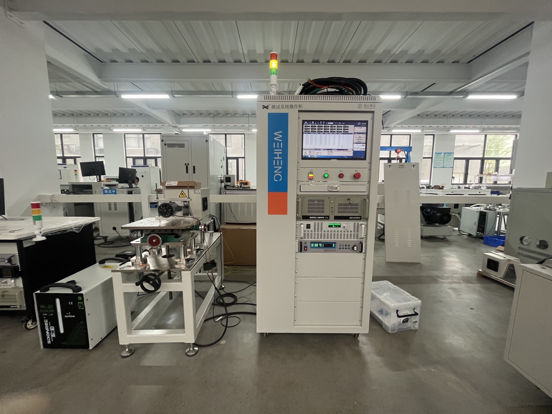
This Weiheng DS motor test station shows a control cabinet, loading fixtures, and supporting test equipment arranged as one working setup. During a project review, confirm the loading profile, mechanical interface, measurement channels, protection logic, and report output together.
Engineering Value
Closed-loop loading and synchronized acquisition produce repeatable data across the complete test sequence.
Run steady-state points, sweeps, cycles, and project-specific loading sequences.
Align mechanical and electrical channels for torque-speed and efficiency analysis.
Match the shaft, coupling, fixture, base, guard, and installation conditions.
FAQ
A dynamometer test bench applies a controlled mechanical load to a motor while measuring torque, speed, electrical input, mechanical output, efficiency, and other performance data.
Selection starts with rated and peak torque, maximum speed, power, test duration, dynamic response, cooling, and the required loading profile.
Yes. Weiheng can design the base, fixture, shaft connection, coupling, guard, alignment structure, and mechanical layout around the motor drawing.
Yes. The software can execute configured load points or sweeps, collect synchronized data, display curves, judge results, and generate reports.
Yes. When buyers use the term dynamic test bench for transient or response testing, Weiheng can configure the dynamometer, inertia, control loop, sampling, fixture, and software around the required torque or speed response. The achievable response depends on the motor, loading unit, coupling, controller, and test method.
Send the motor specification, rated and peak values, maximum speed, test items, load profile, drawing, application, installation country, and laboratory or production requirements.
A reviewable AC induction motor load test normally needs a loading machine sized to the required torque-speed-time envelope, a mechanical coupling and guarded fixture, torque and speed measurement, the motor drive and electrical-power measurement, thermal channels, synchronized acquisition, control software, cooling, and protection. The exact configuration follows the motor, load point, duration, and required evidence.
Request a Proposal
Share the motor specification, rated and peak values, maximum speed, loading profile, duty cycle, mechanical drawing, application, and installation country.