
Direct Answer
How should backlash, lost motion, and stiffness be tested on a robot joint?
Test these metrics by first declaring whether the DUT is a reducer, an unpowered integrated actuator, or a powered joint holding position. Constrain the named input side, apply controlled bidirectional torque at the output, and record synchronized output torque and input/output angle together with direction, position, drive and brake state, fixture behavior, and temperature.
Backlash, lost motion or hysteresis, and torsional stiffness are different outputs from the torque-angle record. Each result needs its own definition, calculation region, sign convention, fixture treatment, repeated-cycle rule, and acceptance limit. Do not replace the measured output angle with motor current or an encoder value from an undeclared measurement plane.
Metric Boundary
Do not use one mechanical metric as a substitute for another.
| Metric | Engineering meaning | Typical stimulus | Required record | Report boundary |
|---|---|---|---|---|
| Backlash | A free-play or direction-reversal effect defined at a named mechanical boundary | Small bidirectional angle or torque reversal under a declared holding or drive state | Input and output angle, torque, direction, brake/servo state, temperature, and repeated cycles | Definition, reference point, direction, load region, calculation method, and repeatability |
| Lost motion / hysteresis | The separation between loading and unloading branches of a bidirectional torque-angle loop | Controlled positive and negative output torque across the agreed region | Synchronized torque-angle loop, direction, preload, position, fixture compliance, and temperature | Named branch-gap or loop metric at a declared torque region; do not report an unlabeled single number |
| Torsional stiffness | The relationship between applied torque and angular deflection over a stated region | Controlled torque steps or ramps with the required side constrained | Torque, input/output angle, fit region, mounting, direction, temperature, and fixture correction | Slope or piecewise method, units, fit range, uncertainty inputs, and acceptance tolerance |
DUT Boundary
Reducer-only, unpowered-actuator, and powered-joint results are not interchangeable.
The complete test boundary belongs in every result. The same physical joint can produce a different torque-angle loop when its reducer input is mechanically locked, when an unpowered motor and brake remain in the load path, or when the controller actively holds position.
| Boundary | Included system | Constraint and measurement | Valid interpretation |
|---|---|---|---|
| Reducer only | Reducer input, output flange, housing, bearings, lubricant state, ratio, and mounting | Input mechanically constrained as agreed; output torque and angle measured at named planes | Reducer behavior only; do not describe it as complete powered-joint behavior |
| Unpowered integrated actuator | Motor, reducer, encoder, brake, housing, bearings, and output interface, with power state declared | External loading at the output; input path held through the stated motor, brake, or fixture boundary | Passive assembly behavior under the recorded electrical, brake, and thermal state |
| Powered joint hold | Complete actuator with drive, firmware, feedback, compensation, limits, and supply condition | Controller holds the commanded state while output torque and angle are recorded | Closed-loop assembly behavior; not directly comparable with a mechanically locked reducer result |
Measurement Workflow
Seven steps from a named mechanical boundary to a reviewable result.
| Step | Required definition and evidence |
|---|---|
| 1. Freeze identity and boundary | Record the DUT, revisions, ratio, included motor/drive/encoder/brake, firmware, mounting, input constraint, output measurement plane, compensation state, and temperature condition. |
| 2. Define the metric | State whether the decision requires backlash, a lost-motion or hysteresis metric, torsional stiffness, or all three. Name the calculation region and units before acquiring data. |
| 3. Characterize the fixture | Document coupling, alignment, fasteners, adapters, input lock, output fixture, reference angle measurement, and the method used to observe or correct fixture compliance. |
| 4. Establish the reference state | Zero the synchronized channels and record position, preload, brake/servo state, temperature, lubricant condition where relevant, safety limits, and any preconditioning sequence. |
| 5. Apply bidirectional loading | Run the agreed positive and negative torque steps or ramps through the required region without changing the declared boundary. Record complete loading and unloading branches. |
| 6. Repeat and validate | Repeat the required cycles and positions, retain invalid-run and retest reasons, and verify that clipping, drift, alarms, motion of the constrained side, or fixture movement did not invalidate the result. |
| 7. Report the evidence | Retain raw synchronized samples, processed curves, sign conventions, filtering, calculation code or version, fixture treatment, uncertainty inputs, exceptions, reviewer, and acceptance decision. |
Fixture and Data Integrity
The fixture can become part of the measured deflection.
Adapters, couplings, fasteners, support structures, shafts, and the input-lock arrangement can twist or move under load. The project should identify how this behavior is observed, bounded, or corrected before attributing all angular deflection to the reducer or joint module.
Use one synchronized time base for torque and angle. Record sign conventions, direction, position, preconditioning, temperature, filtering, controller state, and invalid runs so that loading and unloading branches can be reconstructed and reviewed.
Required Record
Keep the conditions behind every reported number.
- DUT identity, revision, ratio, integrated components, firmware, and mounting orientation
- Mechanical input constraint and output torque/angle measurement planes
- Drive, servo, brake, compensation, supply, current-limit, and safety states
- Torque and angle sign conventions, units, ranges, sampling, synchronization, and filtering
- Fixture, coupling, alignment, fastener, preload, compliance, and correction records
- Position, direction, load region, ramp or step, dwell, cycle count, and preconditioning
- Ambient, housing, lubricant, motor, reducer, and other agreed temperature channels
- Raw sample reference, calculation region, method/version, repeated-run variation, invalid runs, and approval
Interpretation Boundaries
Related mechanical observations still need their own method and evidence.
Weiheng keeps these related observations separate from backlash, lost motion, and torsional stiffness so that one convenient signal is not used as a substitute for a different engineering result.
| Related observation | How to interpret it |
|---|---|
| Bidirectional reducer efficiency | Declare input and output planes, motoring or generating quadrant, direction, speed, torque, thermal state, synchronized power channels, and loss treatment. Do not present it as motor or complete-system efficiency. |
| Wear indicator | Compare declared signals under repeatable conditions and revisions. A trend in torque-angle behavior, vibration, temperature, or current can support investigation but cannot identify root cause or remaining life on its own. |
| Encoder accuracy and repeatability | Use a named reference device and plane, direction, load, thermal state, repeated approach method, and uncertainty boundary. Accuracy, repeatability, complete-joint positioning, and drift are not interchangeable. |
| Output bearing and applied loads | Record axial, radial, and moment load vectors, application points, fixture behavior, speed, torque, and thermal state. Bearing-life or complete robot load-spectrum conclusions require separate project evidence. |
| Fault separation | Correlate electrical, mechanical, thermal, control, and event records across named sensor planes. Do not assign a unique root cause from one signal without inspection or supporting evidence. |
Weiheng Mechanical Method Passports
Keep backdrive, no-load friction, and gear-mesh ripple separate from backlash and stiffness.
These observations can share hardware and synchronized channels, but they do not share one measurand or method. Weiheng defines the decision plane, DUT state, stimulus, processing, invalid-run rule and evidence output before comparing results.
| Method | Measured question | Required boundary | Worksheet |
|---|---|---|---|
| Backdrive torque | External torque needed to initiate or sustain reverse motion at a declared plane and powered/brake state | Separate breakaway from running torque; retain direction, speed/ramp, temperature, brake, controller, fixture and onset/calculation rule | Open v1.0 |
| No-load torque / friction map | Torque required for declared motion with no intentional external process load at the output plane | Map speed, position, direction and thermal state; keep fixture, gravity, cable, brake and controller contributions visible | Open v1.0 |
| Gear-mesh ripple | A named torque, speed, position, vibration, acoustic or current component tied to a verified rotational reference | Declare kinematics, sensor/reference planes, synchronization and processing; one spectral line is not a gear-fault diagnosis | Open v1.0 |
Backdrive torque is not a substitute for running no-load friction. A position-referenced friction pattern is not backlash. A rotational order or spectrum is not proof of gear damage, wear, remaining life or acceptance failure without an approved diagnostic chain.
Weiheng Test-System Context
Connect controlled loading, angle measurement, fixtures, safety, and reporting.
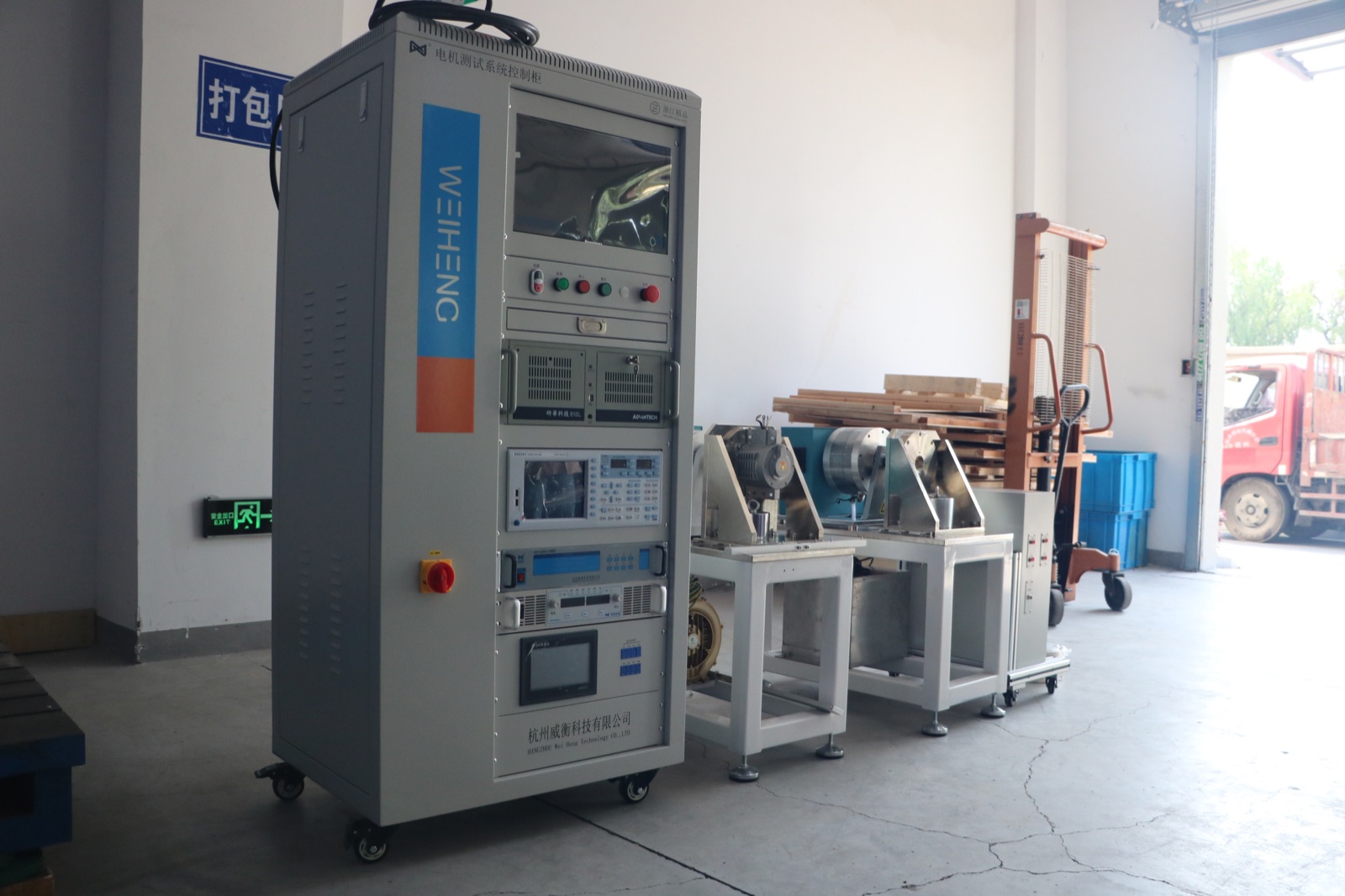
Weiheng can configure robot joint and reducer-related test platforms around the declared DUT, torque region, mechanical interface, input constraint, angle reference, driver or brake state, data channels, and report workflow. The required equipment and method depend on the project boundary and acceptance definition; the factory photograph on this page verifies physical system integration only.
Use the Reducer Test System when the gearbox itself is the DUT, or the Robot Joint Module Test Bench Configuration Guide for the complete actuator and loading platform. Use the Servo Motor Dynamic Response Test Guide when the decision concerns delay, rise, overshoot, settling, tracking, or bandwidth rather than mechanical transmission metrics. Continue to the Robot Joint Thermal and Endurance Test Guide when the project needs duty-cycle, equilibrium, hot-cold, or checkpoint planning. See the Motor Torque-Speed and Efficiency Testing Guide for output curves or efficiency boundaries, and the Robotics and Servo Motor Testing route for the broader application context.
Reference Boundaries
Use public engineering references without turning them into Weiheng specifications.
Harmonic Drive's public Engineering Data illustrates a bidirectional torque-torsion loop and piecewise stiffness regions for its own drive products. Kollmorgen's RGM User Guide shows why a robotic joint boundary may include a motor, drive, brake, strain-wave gear, feedback, thermal sensor, firmware, and duty limits.
These sources support terminology and boundary design. Their model-specific values, test limits, and product performance are not Weiheng specifications and are not copied into a customer acceptance criterion.
FAQ
Robot Joint Backlash and Stiffness Test Questions
Are robot joint backlash, lost motion, and torsional stiffness the same?
No. Backlash describes a direction-reversal or free-play effect under a stated boundary. Lost motion or hysteresis is derived from a bidirectional torque-angle loop using a declared definition. Torsional stiffness relates applied torque to angular deflection over a specified region. One value cannot be substituted for another.
Should the reducer input be locked during a lost-motion test?
The constrained side must be defined, but the correct boundary depends on the engineering question. A reducer-only mechanical lock, an unpowered complete actuator, and a powered joint holding position can produce different results and should not be compared as if they were the same test.
Why must fixture compliance be recorded?
Adapters, couplings, fasteners, shafts, and the input-lock structure can deflect under torque. Without observing or correcting that compliance, the reported angular deflection may include more than the joint or reducer being evaluated.
What data should be retained for a robot joint stiffness test?
Retain synchronized torque and input/output angle samples, direction, position, temperature, drive and brake state, fixture condition, sign conventions, filtering, calculation region, repeated cycles, invalid runs, and the processed torque-angle curve.
What should I send for a robot joint mechanical-metrics test proposal?
Send the joint or reducer drawing, ratio, output torque region, interfaces, encoder and brake details, drive state, required backlash/lost-motion/stiffness definitions, temperature condition, fixture responsibility, report fields, acceptance method, and target country.