
Direct Answer
How do you choose a motor test bench?
Choose a motor test bench by starting with the decision the test must support, then define the DUT, torque-speed-power-time envelope, duty cycle, operating quadrants, interfaces, measurement uncertainty, fixtures, control, safety, software, site, and acceptance method. Compare proposals using calculations, drawings, channel-level evidence, raw-data and report outputs, FAT/SAT criteria, and contract boundaries—not rated power, headline ranges, price, or a fixed headroom percentage alone.
Nine Selection Gates
Choose the complete system, not one headline rating.
| Gate | What to define | Why it changes the selection |
|---|---|---|
| 1. Decision and workflow | R&D characterization, validation, comparison, endurance, troubleshooting, QC, EOL, audit or laboratory service | Determines flexibility, automation, traceability, cycle time, permissions and the acceptance record |
| 2. DUT and complete envelope | Included motor/inverter/controller/module, rated and peak torque, rated and maximum speed, torque-speed combinations, power, direction, quadrants and future variants | Sizes the loading, driveline, power, cooling, protection and measurement chain without combining unrelated maxima |
| 3. Time and thermal duty | Steady points, ramps, steps, reversals, maps, cycles, dwell, overload duration, continuous duration, repeats, warm-up and cooling | Separates peak capability from continuous heat rejection, energy flow and endurance needs |
| 4. Loading and energy path | Absorb-only or motoring/loading operation, regenerative behavior, control modes, response path, power supply, braking and utilities | Selects the loading technology and defines where energy goes in every required operating state |
| 5. Measurement chain | Torque, speed, position, voltage, current, power, temperature and optional channels; ranges, smallest points, accuracy definition, calibration, uncertainty, synchronization and formulas | Shows whether the system can answer the question across the working range, not only display a headline sensor rating |
| 6. Mechanical system | Dimensioned shaft/flange drawings, orientation, coupling, alignment, runout, critical speed, bearing loads, fixture variants, guarding, service and changeover | Defines structural integrity, repeatability, safety, installation and maintainability |
| 7. Control, safety and site | Controller ownership, interfaces, limits, alarms, interlocks, emergency stop, risk inputs, voltage, utilities, cooling, floor, environment and target country | Defines integration, safe states, site readiness and compliance review scope |
| 8. Software and lifecycle | Sequence editing, roles, version/change control, raw data, calculations, reports, languages, barcode/MES, retention, backups, maintenance, expansion and downtime | Determines whether the bench remains auditable and usable after handover |
| 9. Acceptance and contract | Design baseline, FAT, shipment release, SAT, commissioning, training, calibration status, thresholds, invalid runs, retests, deliverables, warranty, support and exclusions | Turns a proposal into a verifiable purchase with named evidence and sign-off responsibilities |
Loading and Measurement
Demand evidence that connects the requirement to the proposed architecture.
| Proposal evidence | Minimum useful content |
|---|---|
| Envelope coverage | Overlay required torque-speed points and durations on the proposed continuous/intermittent loading envelope; show excluded zones, overspeed, overload and future variants. |
| Thermal and energy review | Explain heat rejection, cooling, regenerative or braking path, supply limits and continuous-versus-transient assumptions for the intended sequence. |
| Measurement schedule | List each channel, plane, range, unit, smallest operating point, accuracy expression, calibration status, uncertainty requirement, synchronization and calculation/report output. |
| Mechanical review | Provide fixture/coupling concept, shaft and flange interfaces, orientation, alignment/runout method, speed/guard limits, service access and changeover approach. |
| Control and safety narrative | Define command/feedback ownership, modes, limits, alarms, interlocks, fail-safe behavior, emergency stop, risk inputs and applicable project review. |
| Software and data demonstration | Show the proposed sequence, permissions, live channels, raw export, calculations, curves, report, alarms, traceability, backup and version-control workflow. |
| Acceptance matrix | Map every promised function or performance item to a method, DUT, condition, tolerance, evidence record, invalid-run/retest rule, stage and sign-off owner. |
Reference Boundaries
Maximum ratings, measurement systems and test purpose answer different questions.
Magtrol's dynamometer selection guidance separates maximum torque, maximum speed and maximum power, notes that maximum speed is not full-load speed, and ties power absorption to heat and duration. Its example product ratings do not prove a Weiheng configuration.
Kistler's electric-motor testing overview treats the test bench as a mechanical unit plus sensors, software and evaluation, and distinguishes R&D, endurance, audit, EOL and HiL uses. HBK's electrical-machine measurement guidance shows why synchronized electrical, mechanical and auxiliary channels matter. These sources support selection structure, not Weiheng performance claims.
Common Mistakes
Shortcuts that create technical and acceptance risk.
- Selecting by rated power or three unrelated maximum values instead of a torque-speed-power-time envelope.
- Applying a universal headroom percentage without checking loading technology, thermal duty, resolution, inertia, critical speed and future variants.
- Checking only maximum torque while ignoring the smallest torque or speed points that the measurement chain must resolve.
- Treating the dynamometer, coupling, fixture, power path, measurement, safety, software and cooling as independent purchases without a system boundary.
- Accepting a catalog, screenshot, logo, photograph or certificate collage instead of project-specific calculations, drawings, calibration and acceptance records.
- Combining proposal, design freeze, FAT, SAT and commissioning into one vague approval event.
Limits and Evidence Boundaries
What this guide and photograph do not prove.
- No loading technology is universally best. The correct choice depends on operating quadrants, speed/torque combinations, duration, thermal behavior, response needs, energy path, control method and acceptance question.
- A larger range is not automatically better. Oversizing can affect usable resolution, inertia, cost, fixture scale, safety and efficiency at the buyer's actual operating points.
- A component accuracy, speed or power rating does not prove complete-system performance. Installation, alignment, signal chain, environment, timing, processing and calculation boundaries still matter.
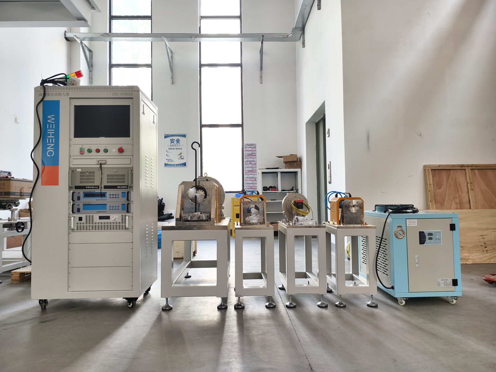
- The original Weiheng photograph proves that branded cabinets, loading equipment, measurement equipment, fixtures and cooling hardware have been physically integrated. It does not prove a range, accuracy, capacity, response, standard, customer or acceptance result.
RFQ Inputs
What should you send before asking for a quotation?
A useful RFQ does not need to be perfect, but it should give engineers enough information to judge the loading method, measurement range, fixture, software workflow, and project complexity.
- Motor type and application
- Rated/peak torque and speed plus the required torque-speed-time points, directions and quadrants
- Power/voltage/current context, controller or drive interface, energy path and cooling method
- Required test items, sequence, duration, repetitions, decisions and acceptance method
- Motor drawing, shaft dimensions, flange, and installation direction
- R&D, laboratory, QC, EOL, or production-line use
- Measurement channels, smallest points, accuracy/calibration/uncertainty needs and raw-data/report fields
- Target country, site conditions, safety inputs, utilities, language and documentation needs
- FAT/SAT, training, support, warranty, change control and contract boundary
Weiheng Approach
Use configuration review before comparing price and delivery.
Weiheng can discuss a system direction from available motor data and documented assumptions, but safety, operating limits, interfaces, measurement definitions and acceptance criteria must be resolved before design release. Review the custom electric motor test bench selection matrix to separate R&D, endurance, EOL, servo and EV project routes; then use the configuration guide for input-to-design logic, the dynamometer guide for loading-envelope review, and the RFQ checklist to prepare the first review.
FAQ
Motor Test Bench Selection Questions
What is the first step in choosing a motor test bench?
Start with the engineering or production decision the test must support, then define the complete DUT and required torque-speed-power-time operating envelope. Equipment selection should follow the test sequence, measurement, safety, software, site and acceptance requirements.
Is rated motor power enough to select a test bench?
No. Rated power does not define peak and continuous torque, maximum speed, torque-speed combinations, quadrants, overload duration, inertia, cooling, transient sequence, smallest measured points, fixture, energy path or acceptance method.
How much torque and speed headroom should a test bench have?
There is no universal percentage. Headroom should be justified against the required operating points, overspeed and overload cases, continuous and intermittent thermal limits, future variants, loading technology, measurement resolution, inertia, mechanical limits and project risk.
What evidence should a supplier provide with a proposal?
Request envelope and thermal calculations, a system boundary, channel schedule, fixture/coupling concept, control and safety narrative, site and utility list, software/data demonstration, and an acceptance matrix linking each promise to a method, condition, tolerance, record and sign-off stage.
Should FAT and SAT use the same checklist?
They may share requirements, but they are not the same stage. FAT verifies agreed scope before shipment under factory conditions; SAT and commissioning address the installed system, buyer interfaces and site conditions. Methods, available equipment, exceptions and sign-off owners should be explicit.
Can one motor test bench cover R&D and EOL testing?
It may be possible, but shared hardware does not make the workflows equivalent. Capacity, cycle time, fixtures, permissions, change control, traceability, maintenance, production interruption, measurement and separate acceptance responsibilities must be reviewed.